はじめに
In this guide, we will show you how to remove and replace the motherboard and LCD.
必要な工具と部品
-
-
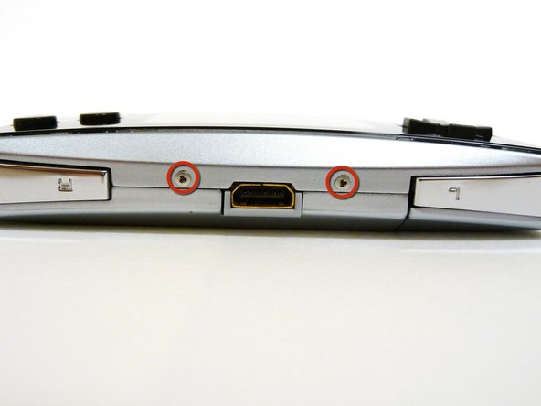
Locate the two circular holes on the side of the Game Boy nearest to the directional pad.
 FixBotに聞いてみる
-
-
-
Straighten the end of a paper clip and push it into each of the circular holes.
-
Use the paper clip to lever the faceplate off from the unit.
-
-
-
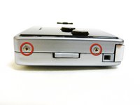
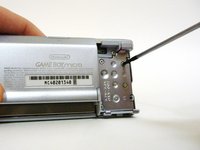
Remove the Phillips #00 screw on the side of the Game Boy closest to the directional pad.
-
Once the screw has been loosened, lift the cover off the back of the device.
-
-
-
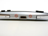
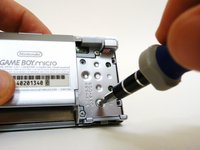
Remove the two tri-wing screws on the top of the Game Boy and the two screws next to the volume/contrast switch.
-
-
-
-
Remove the two Phillips #00 screws from the plastic frame.
-
As you are pulling off the plastic frame, the shoulder buttons and the volume switch may fall out of the device.
-
-
-
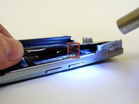
With a spudger, depress the small clip on the lower right corner of the plastic guard.
-
Grab the edges of the plastic frame and lift the frame off the motherboard.
-
-
-
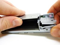
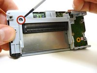
With one hand, gently slide the top left end of the motherboard up and out of the front case.
-
With your other hand, pull out the EMI shield until the tab comes out of the front case.
-
Once the tab is pulled out from the bottom, slide the EMI shield down and out of the device.
-
-
-
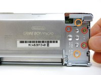
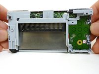
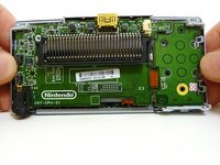
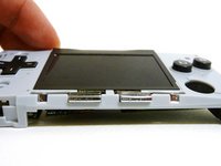
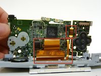
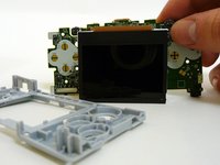
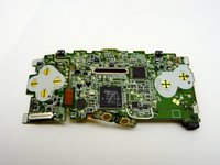
The entire motherboard is now accessible.
-
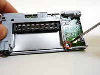
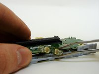
A small ribbon cable connects the start and select buttons to the motherboard. It can rip very easily, so do not pull on it.
-
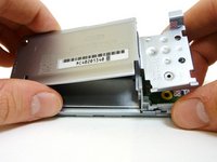
Lift the motherboard and the front plastic cover assembly off of the front case.
-
-
この手順で使用する道具:Tweezers$4.99
-
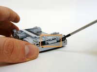
When you remove the motherboard from the front case, the start and select buttons may fall out.
-
If the buttons do not fall out, remove them with a pair of tweezers.
-
-
-
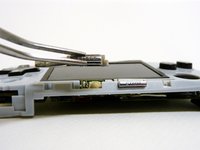
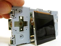
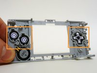
Without the front case, you will be left with the motherboard and the plastic mount. The LCD screen is attached to the motherboard by a ribbon and can fall off the plastic mount.
-
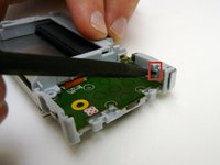
Using metal tweezers, grab the start/select board and slide it out gently.
-
-
-
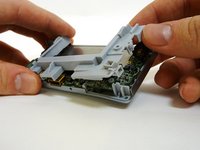
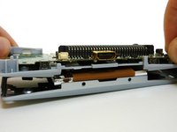
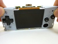
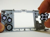
Lift the entire motherboard assembly off the plastic guard.
-
Take caution not to damage any of the gold ribbon cables on the motherboard.
-
-
-
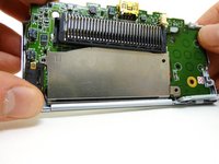
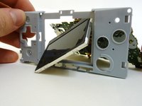
To remove the LCD screen, carefully angle it until it is diagonal to the square hole in the plastic guard and slide it out.
-
It is now possible to remove the entire motherboard assembly from the plastic guard.
-
-
-
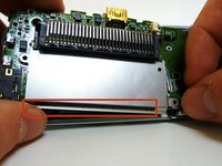
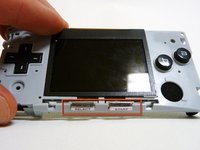
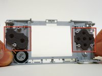
On the plastic guard, there are two rubber pads that cover the buttons. Remove them.
-
With the rubber pads off, you may use your fingers to remove the buttons to clean or replace them.
-
-
-
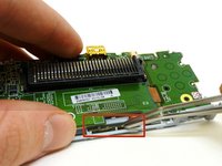
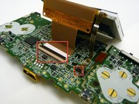
The LCD screen is connected to the motherboard by two ribbon cables.
-
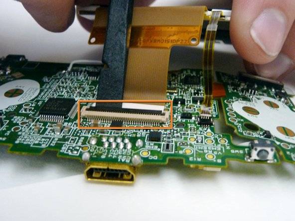
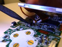
Use a plastic spudger to disconnect the LCD's ZIF connector.
-
-
-
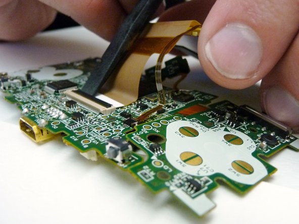
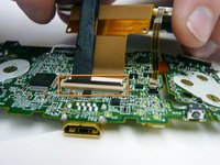
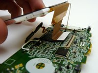
Use the tip of the spudger to lift the small, black tab holding the thin ribbon.
-
With both tabs lifted, pull the ribbons off the motherboard and remove the LCD screen.
-


To reassemble your device, follow these instructions in reverse order.
20 の人々がこのガイドを完成させました。
チーム

Cal Poly, Team 8-46, Regan Winter 2010 Cal Poly, Team 8-46, Regan Winter 2010人のメンバー
CPSU-REGAN-W10S8G46
5 メンバー
25のガイドは作成済み
1件のガイドコメント
Ich wollte vorne das Cover wechseln bei dem gameboy micro und ich habe zu doll in die Löcher reingestochen so das es in drinnen gebrochen ist... Wer kann das reparieren?? Hilfe