メインコンテンツにスキップ

このバージョンは誤った内容を含んでいる可能性があります。最新の承認済みスナップショットに切り替えてください。

必要な工具と部品

  1. この手順は未翻訳です。 翻訳を手伝う。

    : 手順 1、 1の画像 1
    • Remove the six 13 mm case screws with a #0 Phillips screwdriver from the side of the power screwdriver.

  2. この手順は未翻訳です。 翻訳を手伝う。

    : 手順 2、 2の画像 1 : 手順 2、 2の画像 2
    • Using a plastic opening tool, separate the case in two to expose the internals of the cordless screwdriver.

  3. この手順は未翻訳です。 翻訳を手伝う。

    : 手順 3、 3の画像 1 : 手順 3、 3の画像 2 : 手順 3、 3の画像 3
    • Remove printed circuit board, LED, battery, and motor assembly from the screwdriver casing.

    • Use a soldering iron to melt the solder from the LED's two pins on the printed circuit board.

    • Remove the LED from the circuit board while the solder is still melted.

  4. この手順は未翻訳です。 翻訳を手伝う。

    : 手順 4、 2の画像 1 : 手順 4、 2の画像 2
    • Place the positive leg of the new LED through the positive hole in the printed circuit board and solder it into place.

    • Place the negative leg of the LED through the negative hold in the printed circuit board and solder it into place.

ゴール

ある他の人がこのガイドを完成しました。

作成者

5人の作成者と共同で作成されました。

Tyler Vincent

メンバー登録日: 02/24/14

479 ポイント

4のガイドは作成済み

チーム

Michigan Tech, Team 5-5, Lauer Spring 2014 Michigan Tech, Team 5-5, Lauer Spring 2014人のメンバー

MTU-LAUER-S14S5G5

3 メンバー

5のガイドは作成済み

コメント 1 件

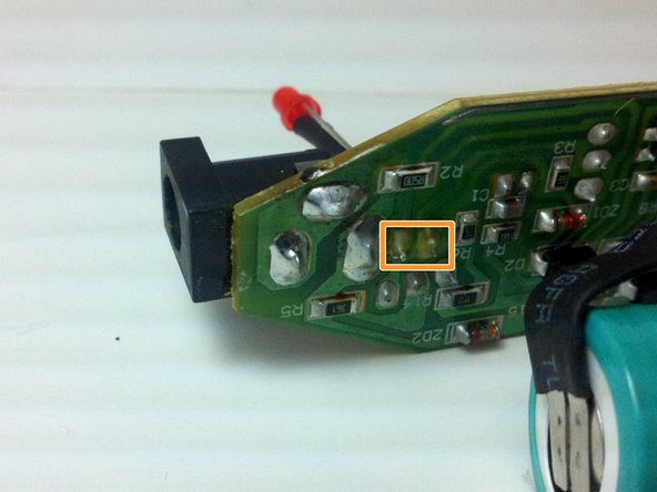
Hello, I would ask the author about the type and model number of the electronic element marked as Q1 on the PCB (transistor or thyristor) on the third picture in Step 3 of this article, because mine is burnt out, and on this picture can't be read anything.

Greetings,

Plam

Пламен Петракиев - 返信

コメントを追加

統計データ:

過去 24時間: 0

過去 7 日: 3

過去 30 日: 6

今までの合計 1,093