Place the radio with the front facing down and the top of the radio facing you.
Remove the seven 6 mm screws holding the cross member in place.
The screw called out in yellow is slightly different than the other screws. The length is the same but it has a tighter thread pitch. Make sure it goes back in the same place.
It is difficult to see all of the circuit board's screws from one angle. This series of photos starts at the top center and moves clockwise around the circuit board.
Screws are only called out when they make their first unobstructed appearance.
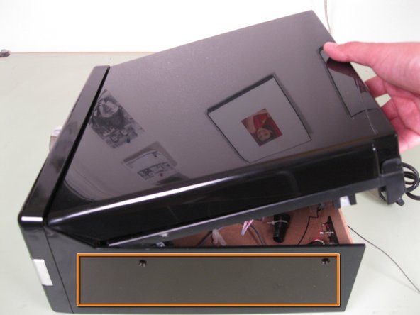
The screw in the black square is not part of the main circuit board and should not be removed.
Remove the ten 4 mm screws holding the circuit board in place.
On both sides place two fingers between the circuit board and the face of the radio.
Gently pull the circuit board straight back being careful not to break the volume and tuning knob posts on the opposite side of the board.
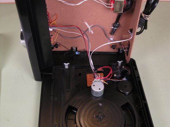
The two white cables are soldered to the circuit board and the power transformer at the back of the radio. Once removed, the circuit board has to be set aside inside the radio.