Solution for missing solder pads
When removing a faulty power switch I accidentally ripped off the power switch with its solder pads still attached. Any available solutions to bypass the missing solder pads?
この質問は役に立ちましたか?
スコア
0
評価: 67
![]() 3
3
![]() 3
3
When removing a faulty power switch I accidentally ripped off the power switch with its solder pads still attached. Any available solutions to bypass the missing solder pads?
この質問は役に立ちましたか?

評価: 96.1千
![]() 154
154
![]() 82
82
![]() 116
116
All right, I found a few posts on the subject and it appears the general consensus is that you only need pins 1 and 2 in order for your switch to work. Going by your photo, it looks to me like pin 1 is intact; that is, the solder pad is still present so you should be able to solder the switch onto that pad.
DS lite Power switch pinout : r/nds
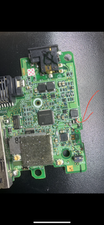
From what I found, one of the pins goes to a test point on the other side of the board labelled PWSW. The other is supposed to be a ground. Here's a picture of the PWSW point.
This post seems to be saying that PWSW goes to pin 1, and if that's the case, you should be good there, since the pad is intact. You can always use an ohmmeter to verify continuity between PWSW and pin 1 to be safe.
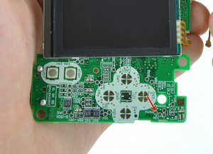
So now you have to find a ground pin to connect pin 2 to. According to that Reddit thread, there's a ground connection nearby.
I'd suggest using the gold square next to the power LEDs as ground since it's close by.
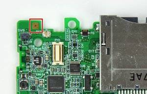
I think that's the square they're talking about; you can easily test it just by shorting pin 1 to that point with a piece of wire. If it works, run a jumper between there and pin 2 on the switch, solder down pin 1 and you should be good.
Oh yeah, since it looks like the two solder mounting points that are supposed to secure the switch to the board appear to be gone as well, you'll probably just want to use some strong adhesive on the whole thing; epoxy, gorilla glue, or whatever that will give a good solid bond to hold the switch down permanently.
Hope that helps; let us know what you find!
このアンサーは役に立ちましたか?
I’ll definitely try this out and see if it turns out well.
Seems to have fixed the issue. Thanks!
I accidently ripped pads 2, 3 and 4 off trying to remove the old power switch.
Soldered the new power switch to the main posts and pad one.
Soldered a wire to the leg for pad 2, and soldered it to the gold square next to the power LEDs
Was able to curve the wire around the post so the shell could solidly close.
Works perfectly.
THANK YOU!
評価: 151
![]() 3
3
Yes, there is a solution if you are taking about through hole components. A surface mount board means there will be no where to mount the switch. Place the switch onto the circuit board and using very thin wire, solder the wire to the switch terminal. Follow the circuit trace to the next solder pad and solder the remaining wire end to this pad. Repeat this procedure for every switch terminal that gets used. Not all the terminals may be used. Make sure you have thin wire (no larger than 22AWG, 30AWG is probably better) thin solder intended for circuit board applications and you have proper soldering skills.
このアンサーは役に立ちましたか?
I don’t see any traces on the board that leads to the missing pads.
No traces means those pads are not required unless the board has intermediate layers. Try ignoring those and solder to the remaining pads.
過去 24時間: 1
過去 7 日: 13
過去 30 日: 64
今までの合計 1,718