Bailey S if the voltages are truly as high as you are saying, then yes, its a power board issue. I would check the transformers as well as the components around it. ? If you let us know the exact model of this TV we can probably verify all of this better. Of course, you can also add some images of your boards with your QUESTION so that we can see what you see. If you mark where you checked the voltages, we can double check and verify. Ultimately, voltages to high-power board
iFixitでの質問に画像を追加する方法
Bailey S see if this makes sense and if you can follow along those steps of the power on sequence:
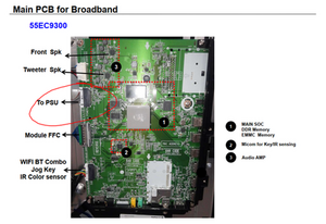
TV Turn On Commands (Explained) 55EC9300 OLED (2014) Power Supply Section 05
(1) When AC is applied to the SMPS, it outputs 3.5V_ST to the Main board, P2300 pins 3, 5 and 6. This 3.5V is routed through L2304 and on to the Microprocessor IC3000 pin 48 as its main power source. The 3.5V also goes to the Reset circuit. At the moment 3.5V arrives at C3004 (+) side, the capacitor isn’t charged, so pin 40 of the Micro is low while the power input pin 48 is high. This is known as the reset state, where the Microprocessor is reset to the first operational state. As C3004 charges through R3030, pin 40 pulls up and the Micro comes out of Reset. The TV is now in the Stand-By state. The 3.5V is also routed to pull-up resistors to the Key 1 and 2 lines. It is also sent to the IR receiver and as source voltage for the Power on switch Q2300, but it is not on at this time.
(2) When the Power on key is pressed on the Joy Stick (Press in and hold), pin 31 of the Micro drops. This notifies the Micro that the TV should turn on. If the Power On key on the Customer’s Remote is pressed, The IR receiver sends this signal (3.4V p/p) to the Microprocessor pin 6 and the TV knows by this signal to turn on.
(3) The Micro outputs a low on pin 36 (RL_ON) which is routed to pin 2 of Q2300 turning it on. The 3.5V on pin 1 is then switched out pin 3 and on to the SMPS via pin 1 of P2300. The Controller on the SMPS receives this command and turns on the 12V and the 24V.
(4) The 12V and 24V lines are routed to the Main board via P2300, 24V pins 9, 10 and 16 and 12V pins 13, 14 and 15. The 24V is used for the two Audio amplifiers as their amplification voltage.
(5) The 12V is routed to many different regulators (too many to mention here), but for this “Power On Cycle” discussion it goes through coil L2303, then L12007, then L1401 and out P11401 pins 1-4 to the T-CON board.
(6) The 12V also routed to IC2307 (Power Detector). This IC then outputs a high to the Micro pin 14 to notify the Micro that the voltage arrived. So the Micro can continue turning on the rest of the set. If missing, the TV will click on and then Click off. This fault shows up in the Power Off Status as “5VMNT”.
(7) Once the Micro knows the 12V has arrived, it outputs a high on pin 15 which is routed to pin 1 of IC2300 turning it on. This IC is the +3.3V_NORMAL regulator. This 3.3V is routed to many different circuits, but one of them is as a pull-up voltage through R2310 to the INV_CTL (DRV_ON) line. However, the Micro is holding “INV_CTL” low via pin 19 at this time.
(8) The next step for the Micro to release the low on pin 19 and allow the “INV_CTL” line, (Inverter Control) to pull high, (approximately 3.5V). This high leaves P2300 pin 2 and now becomes DRV_ON (Drive On). When this high arrives on the SMPS controller IC, the controller turns on the Panel 24V line which is output P202 (pins 8-14) and on to the T-CON board CN7. This voltage is then routed through the T-CON and out to the Panel itself for the Panel’s operational voltage.
NOTE: The Panel 24V is monitored by the Main board. There is a line on the Vx1 cable P11401 pin 20 called MODULE 20V DET. This line is normally 3.29V when the 24V is normal. If the 24V is missing or low, this line drops, pulling pin 44 of the Microprocessor low. Then the TV shuts off and logs “POWER_OFF_BY_20V_DET in the Power Off Status in IN-START Menu.
Power Supply Board Low Voltage Test 1
AC Should not be applied at any time while adding jumpers or While unplugging connectors as damage to the circuit Board may occur.
a) When AC is applied, the SMPS “MUST” be producing STBY 3.5V on pins 3 and 5 of P201.
If 3.5V Standby is not being generated, the SMPS is defective and must be replaced. There is no need to continue with the next test. But, make sure AC is arriving at the connector SK100 and +3.5V_ST is not loaded down by the Main Board or the IR or the Joy Stick Boards.
( b) Unplug P2300 on the Main Board to make insertion of the Jumpers easier.
Use P2300 side to insert resistors
TEST 1: Testing the Power Supply turn on circuit.
(1) (A) Add a jumper between (3.5V STBY) pin 3 or 5 and Pin 1 (PWR_ON).
Apply AC, (See Fig 1). This will turn on the SMPS, relay click will be heard.
Check that the 24V and 12V power supplies are turned on,
Main Board Power:
• P2300 (12.07V pins 13, 14 and 15)
• P2300 (23.28V pins 9, 10 _


1件のコメント
Hello, I have a similar problem with the same model of LG TV that I just pick up. Would it be possible to point me to the link to download the correct service manual / schematic? Thank you very much for your help.
pchien さんによる