I guess there might be a dry joint on the connector or something, or perhaps a hairline crack in the board - this might have happened if the crash tore that motor off, pulling violently on the cable, or if you were very careless about unplugging it, possibly - you’ll need to examine the board very closely and trace the signals back from the connector and test with a meter to establish that.
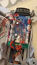
Probably more likely though that the FETs supplying that motor have expired because of overcurrent when the motor jammed - again, you’ll need to trace things around and work out what the motor connections are connected to - can’t see anything on top of the board that looks like FETs for the motor channels, each one appears to have a fairly robust looking diode associated (e.g. D2) but those will probably not be broken. Maybe the 8-pin packages underneath the board might be H-bridges or multi-FET packages or something. An oscilloscope would really help to track down the problem, because you could see for sure whether the control signal was getting to the FET, whether the FET was working, etc. If you can identify the driver for the channel you could try replacing it but it’s likely to be fiddly.
I don’t know if you can get the flight controller board as a spare, but I’m guessing it’s the same as in the 2k camera version of the same drone and I think those can be obtained pretty cheaply - might be an idea to lay in a spare drone (perhaps a s/h crashed one) to cannibalise for a controller board, and then repair the original board at your leisure.


6 件のコメント
Just want to make sure I understand you correctly, so you have tried a motor that doesn't work on one mount but it works on the other ones?
Please add some pictures of the mount, connections and circuit board, it will help to understand what the problem may be. iFixitでの質問に画像を追加する方法
Erik Eriksson さんによる
Hi thanks for the reply. I bought a new motor and cog as the other was dead. Built it up in the arm. Doesnt work in the plug. But if I plug it in to the motor the other side it spins. So know its not the motor.
I cannot see anything obvious with the board. Will post some pics.
Colin Branagh さんによる
@Colin Branagh
How does it look if you unplug the connector, can you see any bent/dirty pins?
Erik Eriksson さんによる
Found this looks like its exploded
Colin Branagh さんによる
@Colin Branagh
Can you add a picture on it?
Erik Eriksson さんによる
1以上のコメントを表示