注意:あなたはさきほど閲覧しているガイドの前提となるページを編集しています。あなたが行った変更は、この手順を含むガイド全体に影響を与えます。
手順 28を翻訳中
手順28


-
Remove the following five screws securing the logic board to the upper case:
-
Four 3 mm Phillips screws.
-
One 3.5 mm Phillips screw.
-
Remove the two 7 mm Phillips screws securing the DC-in board to the upper case.
-
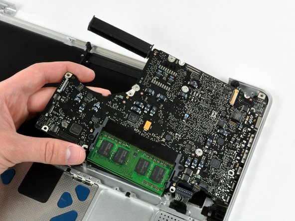
Lift the logic board from its left edge and pull it out of the upper case.
クリエイティブコモンズのオープンソース著作権のもと、あなたの投稿は著作権の対象となります。