注意:あなたは必要条件ガイドを編集しています。あなたが行なう変更は、この手順を含む全ての9個のガイドに反映されます。
手順 6を翻訳中
手順6
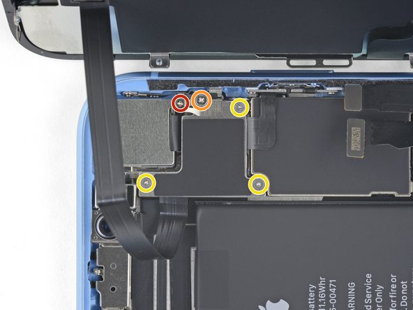


Unscrew the logic board connector cover
-
Remove the five screws securing the logic board connector bracket to the rear case:
-
One 1.3 mm Phillips #000 screw
-
One 1.5 mm Phillips #000 screw
-
Three 1.2 mm Y000 screws
-
Remove the bracket.
クリエイティブコモンズのオープンソース著作権のもと、あなたの投稿は著作権の対象となります。