この翻訳は、ソースガイドの最新の更新を反映していない可能性があります。 翻訳の更新に協力してください。 または ソースガイドを参照してください。
はじめに
必須条件のみ
必要な工具と部品
-
-
-
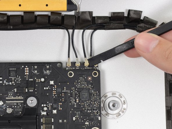
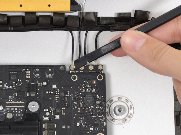
スパッジャーの平面側先端を使ってAirPort/Bluetoothカードから4本のアンテナコネクタの各接続を外します。
I broke off one of the antenna connectors when I took off the antenna wires, but the new 802.11ac card is working:) I seems the way to take off the wires is lifting it up from the wire side. In hindsight I just wasn´t careful enough.
how do I check a working logic board
If you have a pair of angled tweezers, they work well for grabbing under the connector so that you aren’t pulling on the wire. The head of the T10 screwdriver works well for pressing them back on.
iMac 2017 EMC 3069 this has the antenna brackets with two T5
-
-
-
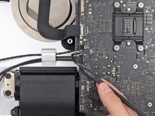
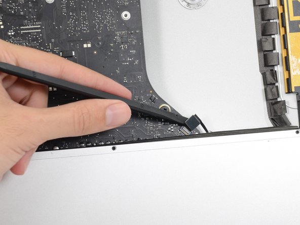
スパッジャーの平面側先端を使って、ロジックボード上の基板からヘッドホンジャックのケーブルコネクタを引き抜きます。
Unlike the rest of the connectors on the logic board, this one lifts up away from the board rather than to the side. That “Push the cable slightly to the right.” notation is after the connector is free.
-
-
-
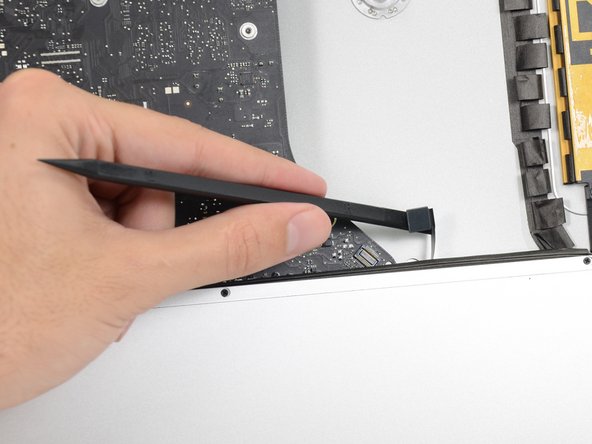
リアエンクロージャーに排気ダクトを固定している次のネジを外します。
-
6.3 mm T8ネジー2本
-
4.7 mm T8ネジー2本
Weirdly, these screws didn’t work with my T8 driver. Not with T6 or T10.
Every other screw (to this point) has been fine. Hmm.
??? The T8 worked fine for me. Not sure what the difference would be.
Fare molta attenzione alla vite in fondo a destra, è facile (soprattutto se la punta del proprio cacciavite non è magnetizzata) che la vite si perda sotto alla Logic board. Se la punta del cacciavite non è magnetizzata consiglio o di utilizzare un magnete esterno o di utilizzare delle pinze mentre si svita la vite in modo da non incorrere in questo problema.
-
-
-
リアエンクロージャーにロジックボードを固定している7.2 mm T10ネジを4本外します。
When reinstalling the logic board, install four screws loose. Insert thumb drives into the back in all slots to ensure alignment. Once aligned, then tighten screws.
Gary Kelch - 返信
On some models there is a tiny microphone cable connector, just above the lower left logic board screw. Remove by carefully pulling straight down. There is also a piece of insulating plastic w/adhesive on top of the screw which can be pulled off prior to removal. Save and reuse with the same screw on installation.
-
-
-
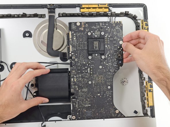
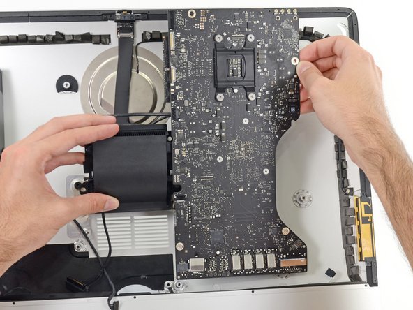
ロジックボードをリアエンクロージャーから離すように傾けます。
-
ロジックボードをiMacからまっすぐ持ち上げて取り出します。
When inserting the logic board back, pay attention of the position of the I/O connectors. When it is back in place, put a USB / Thunderbolt cable into the connectors to ensure the perfect alignment.
This is fantastic advice. I used a combination of USB and display port plugs to ensure proper alignment and help keep the logic board steady while i screwed it back in. Thank you!!
kazoodac -
ive gotten this far and i still have one question, i’m replacing my HDD With A SSD should i also remove the original Blade drive ? and run exclusively off the ssd, ? i wasn’t 100 on whether or not i was getting the fusion set up so i’m not in possession of a upgraded blade, so i though this was a good question id hadn’t seen asked.
-


デバイスを再組み立てする際は、これらのインストラクションを逆の順番に従って作業を進めてください。
デバイスを再組み立てする際は、これらのインストラクションを逆の順番に従って作業を進めてください。
以下の翻訳者の皆さんにお礼を申し上げます:
85%

Midori Doiさんは世界中で修理する私たちを助けてくれています! あなたも貢献してみませんか?
翻訳を始める ›


As noted in the right speaker cable section, the two corners of the connector are latches that need to be pushed toward the center of the connector to release. This is easily done with the pointed end of the spudger. Once the two corner latches are released, the connector comes apart easily.
Fred Heineman - 返信