この翻訳は、ソースガイドの最新の更新を反映していない可能性があります。 翻訳の更新に協力してください。 または ソースガイドを参照してください。
はじめに
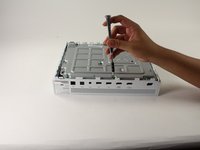
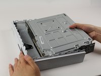
交換が必要なマザーボード上の特定の部品にアクセス必要があるため、このガイドは重要です。
必要な工具と部品
-
-
-
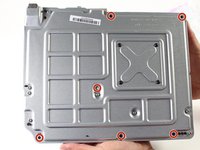
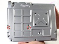
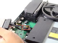
マザーボードを交換するには、「C1」、「C2」、「C6」と表記された銀色の10 ㎜ T-10トルクスネジ3本を取り外す必要があります。
-
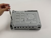
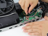
「A1」「A2」「A3」「A4」と表記された黒い8 ㎜ T-9トルクスネジ4本を取り外します。
-


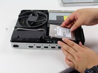


元通りに組み立てるには、これらの手順を逆に実行します。
元通りに組み立てるには、これらの手順を逆に実行します。
61 の人々がこのガイドを完成させました。
以下の翻訳者の皆さんにお礼を申し上げます:
41%

prednin5mgさんは世界中で修理する私たちを助けてくれています! あなたも貢献してみませんか?
翻訳を始める ›
チーム

Cal Poly, Team S22-G3, Livingston Spring 2017 Cal Poly, Team S22-G3, Livingston Spring 2017人のメンバー
CPSU-LIVINGSTON-S17S22G3
4 メンバー
59のガイドは作成済み
10 件のコメント
This guide is really missing alot between steps 13 and 14. There are two black panels that have to be removed(they’re in the teardown guide). One is on the front with with screws E1 ,E2, E3, E4. And theres another panel on the side with screws D1, D2, D3. Finally there are two more screws on the bottom that hold down the motherboard B1, and B2. Theres Also a black from in between the Fan and case that slides off too.
Yep, I was using this guide and realized that it is missing a few vital steps. Thank you Nathan.
If you have a multimeter could you please test the test points around the board and give me a list of a voltages?
fantastic! only issues that are missing, are mentioned in the comments above. I´d like to include that most of the exterior hardcase clips are made to be HELD in place. Which is why it´s a nuisanse to remove. So, newcomers be careful with it. otherwise you´ll easily break it.
Son los mejores