メインコンテンツにスキップ

Welding technique: How to replace the joystick potentiometer

必要な工具と部品

ビデオの概要

  1. Welding technique: How to replace the joystick potentiometer, Battery Pack: 手順 1、 1の画像 1
    • Remove the battery pack cover.

    • Remove batteries.

  2. Welding technique: How to replace the joystick potentiometer, Side Handles: 手順 2、 2の画像 1 Welding technique: How to replace the joystick potentiometer, Side Handles: 手順 2、 2の画像 2
    • We recommend using a nylon spudger for this step. A metal spudger is shown.

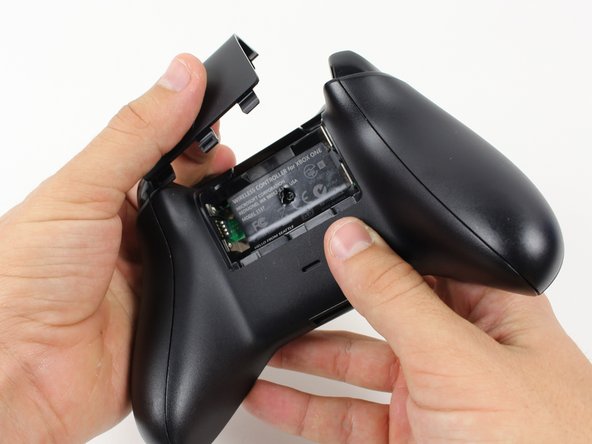
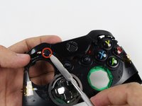
    • Grip the controller firmly to remove the side handles, wedging a spudger into the seam between the front and handle plates.

    • Pry the side plate away from the front plate by moving the spudger back and forth. You will need to do this all the way around the side plate's seam.

  3. Welding technique: How to replace the joystick potentiometer, Screws: 手順 3、 2の画像 1 Welding technique: How to replace the joystick potentiometer, Screws: 手順 3、 2の画像 2
    • There is a hidden screw located in the middle of the controller behind the label.

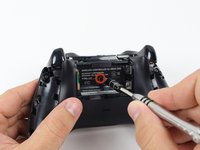
    • Use a screwdriver and punch a hole directly in the center of the label.

    • You may also lift the label if you do not want to puncture it.

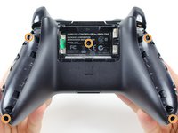
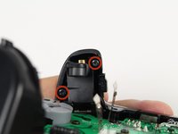
    • Remove the five 10mm screws located on the back of the controller using the TR8 Security Torx Screwdriver.

  4. Welding technique: How to replace the joystick potentiometer, Backplate: 手順 4、 1の画像 1
    • Remove the backplate.

  5. Welding technique: How to replace the joystick potentiometer, Faceplate: 手順 5、 1の画像 1
    • Remove the faceplate.

  6. Welding technique: How to replace the joystick potentiometer, Top Motherboard: 手順 6、 2の画像 1 Welding technique: How to replace the joystick potentiometer, Top Motherboard: 手順 6、 2の画像 2
    • You may let the rumble motors hang freely out of their sockets.

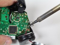
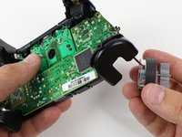
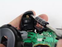
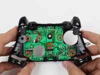
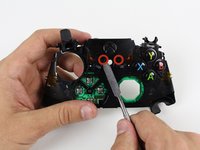
    • De-solder the soldered joints while holding the red and black wires down on the top motherboard.

    • De-solder the black and gray wires that are attached to the top motherboard.

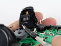
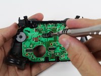
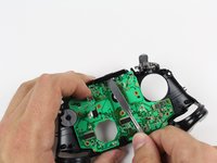
    • Remove the rumble motors and set them aside.

    • Be careful while using the soldering iron not to damage other components or hurt yourself.

    • For information on how to solder, click here.

  7. Welding technique: How to replace the joystick potentiometer: 手順 7、 1の画像 1
    • Unscrew the two 7mm T6 screws located near the rumble motor sockets.

  8. Welding technique: How to replace the joystick potentiometer: 手順 8、 1の画像 1
    • Firmly grip sides of motherboard near the middle.

    • Lift upwards while slightly wiggling the motherboard forward and backward.

    • Lifting the motherboard will require some force.

  9. Welding technique: How to replace the joystick potentiometer, Trigger Rumble Motors: 手順 9、 1の画像 1
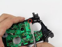
    • Remove the yellow tape holding the wires in place on the front of the controller.

  10. Welding technique: How to replace the joystick potentiometer: 手順 10、 3の画像 1 Welding technique: How to replace the joystick potentiometer: 手順 10、 3の画像 2 Welding technique: How to replace the joystick potentiometer: 手順 10、 3の画像 3
    • Unscrew the two 7mm T6 Hex screws located on underside the triggers.

  11. Welding technique: How to replace the joystick potentiometer: 手順 11、 1の画像 1
    • Remove the trigger covers.

  12. Welding technique: How to replace the joystick potentiometer: 手順 12、 1の画像 1
    • Desolder the wires from the motherboard.

    • Remove the rumble motors from its socket and pull the wire with it.

  13. Welding technique: How to replace the joystick potentiometer, Bottom Motherboard: 手順 13、 2の画像 1 Welding technique: How to replace the joystick potentiometer, Bottom Motherboard: 手順 13、 2の画像 2
    • Remove the six T6 Torx screws located on the bottom motherboard.

  14. Welding technique: How to replace the joystick potentiometer: 手順 14、 2の画像 1 Welding technique: How to replace the joystick potentiometer: 手順 14、 2の画像 2
    • Remove the bumpers by prying them off of the pegs that secure them, using a spudger. They are located on the front and back of the controller.

    • A standard nylon spudger is recommended for this step. Using a metal spudger near the motherboard as shown risks damaging your device.

  15. Welding technique: How to replace the joystick potentiometer: 手順 15、 2の画像 1 Welding technique: How to replace the joystick potentiometer: 手順 15、 2の画像 2
    • Lift the piece surrounding the Home button off of its pegs.

    • Pry it off of the other side, using a spudger on the pins.

    • A standard nylon spudger is recommended for this step. Using a metal spudger near the motherboard as shown risks damaging your device.

    • Removing this piece may require a lot of force.

  16. Welding technique: How to replace the joystick potentiometer: 手順 16、 1の画像 1
    • Remove the bottom motherboard.

終わりに

To reassemble your device, follow these instructions in reverse order.

3 の人々がこのガイドを完成させました。

作成者

3人の作成者と共同で作成されました。

@HectorNavarroMX

メンバー登録日: 06/25/18

3,915 ポイント

26のガイドは作成済み

4 件のコメント

Do you know where we can get the original analogue module for the joystick?

Farhan Feroze - 返信

it does not exists, so you should buy generic replacement spare part

@HectorNavarroMX -

I love welding technics. This post has clear ideas on how to replace the joystick and shows in detail that’s I like it. I also try to fix many things, and it’s delightful. Thanks for sharing your ideas.

Anthony - 返信

I just created welding related blog and you will find here more: bestmigwelders.org

Anthony - 返信

コメントを追加

統計データ:

過去 24時間: 5

過去 7 日: 28

過去 30 日: 124

今までの合計 6,040