メインコンテンツにスキップ

Weinmann VENTImotion and VENTIlogic Control Board Replacement

医療機器
この修理ガイドは医療機器メーカーからの是認を得ておらず、iFixitと医療機器メーカーは提携していません。

必要な工具と部品

  1. Weinmann VENTImotion and VENTIlogic Control Board Replacement, Control Board: 手順 1、 1の画像 1
    • Open the device

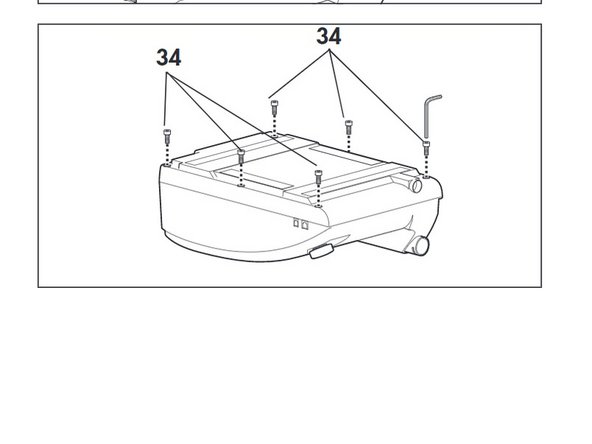
    • 1) Place the device on a non-slip surface with the top facing downwards.

    • 2) Remove the filter cassette from the top part of the housing.

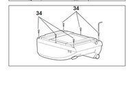
    • 3) Undo and remove the 6 screws (34)

  2. Weinmann VENTImotion and VENTIlogic Control Board Replacement: 手順 3、 1の画像 1
    • Disconnect the following

    • - encoder connector (82)

    • -connectors of interfaces (84) and (85) of the control board.

  3. Weinmann VENTImotion and VENTIlogic Control Board Replacement: 手順 4、 1の画像 1
    • Disconnect the ribbon cable of the display and the fascia film:

    • Pull the latch out until you feel resistance. You can then pull out the ribbon cable.

    • If the latch has not been opened correctly, the ribbon cable may be damaged when it is pulled out.

  4. Weinmann VENTImotion and VENTIlogic Control Board Replacement: 手順 5、 1の画像 1
    • Pull flow measurement hoses (56) off the flow sensor.

  5. Weinmann VENTImotion and VENTIlogic Control Board Replacement: 手順 6、 1の画像 1
    • Pull pressure measurement hoses (57) off the pressure sensors.

  6. Weinmann VENTImotion and VENTIlogic Control Board Replacement: 手順 7、 1の画像 1
    • Insert a new battery (52) in the appropriate holder of the new control board

    • Screw on spring (54)

  7. Weinmann VENTImotion and VENTIlogic Control Board Replacement: 手順 8、 1の画像 1
    • Put the control board in the top part of the housing and attach it with the four screws (51)

  8. Weinmann VENTImotion and VENTIlogic Control Board Replacement: 手順 9、 1の画像 1
    • Reattach the pressure measurement hoses (57) to the pressure sensors.

    • Connect the flow sensor marked Hi to the hose connector marked Hi at the device outlet.

  9. Weinmann VENTImotion and VENTIlogic Control Board Replacement: 手順 10、 1の画像 1
    • Attach the flow measurement hoses (56) to the flow sensor

    • Connect the connection of the flow sensor marked Lo to the hose connector marked Lo at the device outlet.

  10. Weinmann VENTImotion and VENTIlogic Control Board Replacement: 手順 11、 1の画像 1
    • To prevent the hoses from kinking, position flow measurement hoses (56) and pressure measurement hoses (57) as shown.

  11. Weinmann VENTImotion and VENTIlogic Control Board Replacement: 手順 12、 1の画像 1
    • Connect the ribbon cable for the fascia film and the display to the control board again:

    • –pull the latch upwards.

    • –push the ribbon cable into the connector.

    • –press the latch back down

  12. Weinmann VENTImotion and VENTIlogic Control Board Replacement: 手順 13、 1の画像 1
    • Plug the connectors of the interfaces and the rotary knob into the appropriate slots of the control board.

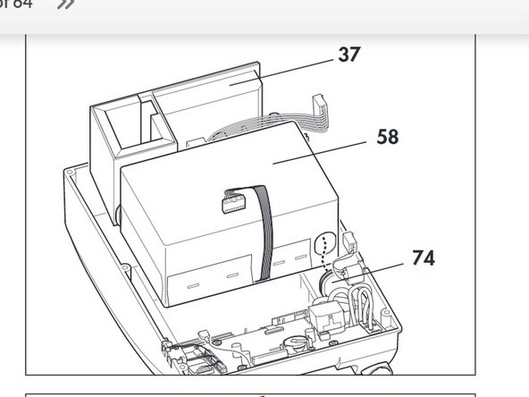
  13. Weinmann VENTImotion and VENTIlogic Control Board Replacement: 手順 14、 2の画像 1 Weinmann VENTImotion and VENTIlogic Control Board Replacement: 手順 14、 2の画像 2
    • Refit the box and filter holder.

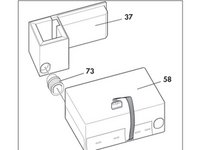
    • Connect the box and the filter holder to one another by reconnecting the intake side hose (73) from both parts.

    • Refit box (58) and filter holder (37) back on the top part of the housing together.

    • Connect the pressure-side hose (74) from the box.

  14. Weinmann VENTImotion and VENTIlogic Control Board Replacement: 手順 16、 2の画像 1 Weinmann VENTImotion and VENTIlogic Control Board Replacement: 手順 16、 2の画像 2
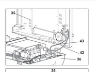
    • Close the Device: Hold the bottom part of the housing (35) up to the side of the top part of the housing (36)

    • Plug the connecting cables for the humidifier (42) and the alarm (43) onto the relevant connectors.

    • Check that all hoses and cables are plugged on firmly.

    • Place the bottom part of the housing (35) on the top part of the housing (36). Ensure that no cables or hoses are trapped or bent.

    • Now screw the top part of the housing tight using the 6 screws (34).

    • Then turn the device back over

    • Check contrast and adjust if necessary .

    • Reset the date and time.

    • Set the date as follows: Year, Month, Day

終わりに

To reassemble your device, follow these instructions in reverse order.

ある他の人がこのガイドを完成しました。

作成者

2人の作成者と共同で作成されました。

Jay Vidinoff

メンバー登録日: 04/07/20

610 ポイント

2のガイドは作成済み

チーム

Cal Poly, Team S7-G19, Paton Spring 2020 Cal Poly, Team S7-G19, Paton Spring 2020人のメンバー

CPSU-PATON-S20S7G19

3 メンバー

4のガイドは作成済み

0 件のコメント

コメントを追加

統計データ:

過去 24時間: 0

過去 7 日: 0

過去 30 日: 5

今までの合計 143