-
-
-
-
On the right side of the camera, remove the two silver screws using the screwdriver.
-
The picture shows the lens facing away from you and the LCD screen facing you.
-
-
On the left side of the camera, remove the two silver screws using the screwdriver.
-
The picture shows the lens facing away from you and the LCD screen facing you.
-
-
-
-
-
-
Keep track of the small screws that you remove.
-
Opening, removing, and/or replacing the front casing may void your manufacturer's warranty.
-
-
-
-
After popping open the plastic piece, there is a screw that needs to be removed.
-
Remove the screw connecting the front casing to the electrical components.
-
-
On the casing on the opposite side of the camera, gently loosen and remove the casing by firmly pulling with your fingers.
-
Be cautious not to break the fragile pieces or scratch the LCD screen.
-
-
-
-
-
The last screw is in the bottom left corner of the camera's right side.
-
Using a screwdriver, remove the last screw holding the LCD/control panel to the rest of the camera on the right-hand side.
-
It is crucial for reassembly to track which screws were removed from which holes.
-
-
At this point, all screws on the left and right sides of the camera should be removed.
-
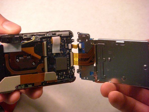
Paying careful attention to the right side's electrical wiring, gently pull the left side of the LCD plate away from the rest of the camera.
-
DO NOT detach the electrical wiring connecting the right side of the LCD and the camera.
-
-
This picture is used to identify the action required to release the electrical ribbons, but not the proper location for this step.
-
This step applies to the larger electrical ribbon connecting the LCD screen and circuit board.
-
Using a spudger, wedge the flat-tipped end between the black bar and the circuit board.
-
Carefully lift the black bar into the vertical position.
-
![: 手順 19、 1の画像 1]()

この手順で使用する道具:
Tweezers
$4.99
購入する
-
After raising the black bar, the electrical ribbon should be free from its port.
-
Use tweezers to carefully pull the larger electrical ribbon from its circuit board port.
-
-
The smaller electrical ribbon, to the left of the larger ribbon, does not have a black bar securing it in place.
-
Use tweezers to pull the smaller electrical ribbon carefully from its circuit board port.
-
このガイドを埋め込む
サイズを選択し、以下のコードをコピーして、このガイドを小さなウィジェットとしてサイト/フォーラムに埋め込みます。
プレビュー