メインコンテンツにスキップ

このバージョンは誤った内容を含んでいる可能性があります。最新の承認済みスナップショットに切り替えてください。

必要な工具と部品

  1. この手順は未翻訳です。 翻訳を手伝う。

    : 手順 1、 1の画像 1
    • Make sure the camera is powered off

    • Turn the camera upside down. This is a view of the bottom of the camera.

  2. この手順は未翻訳です。 翻訳を手伝う。

    : 手順 2、 1の画像 1
    • Push battery cover away from the camera.

  3. この手順は未翻訳です。 翻訳を手伝う。

    : 手順 3、 1の画像 1
    • Push the blue tab that secures the battery. The battery will then spring out.

  4. この手順は未翻訳です。 翻訳を手伝う。

    : 手順 4、 2の画像 1 : 手順 4、 2の画像 2
    • Remove the battery.

  5. この手順は未翻訳です。 翻訳を手伝う。

    : 手順 5、 1の画像 1
    • Working on your device while it is turned on may result in electric shock. Make sure to shut down the camera, remove the battery, and unplug your device before you begin.

    • Use a Phillips head screwdriver to remove one 2 cm screw located on the inside portion of the LCD hinge.

  6. この手順は未翻訳です。 翻訳を手伝う。

    : 手順 6、 2の画像 1 : 手順 6、 2の画像 2
    • While using a plastic opening tool, carefully remove the plastic housing that surrounds the hinge.

  7. この手順は未翻訳です。 翻訳を手伝う。

    : 手順 7、 2の画像 1 : 手順 7、 2の画像 2
    • Using a small Phillips head screwdriver, remove the (2) 2 cm screws on the back of the LCD display, as indicated in the photo.

    • Turn the camera on its side to access the last remaining 2 cm Phillips head screw holding the LCD case together.

  8. この手順は未翻訳です。 翻訳を手伝う。

    : 手順 8、 1の画像 1
    • Remove the plastic cover from the back of the LCD display by simply sliding it up and off of the camera.

  9. この手順は未翻訳です。 翻訳を手伝う。

    : 手順 9、 2の画像 1 : 手順 9、 2の画像 2
    • Using a plastic opening tool, carefully remove the plastic housing that surrounds the LCD display.

  10. この手順は未翻訳です。 翻訳を手伝う。

    : 手順 10、 3の画像 1 : 手順 10、 3の画像 2 : 手順 10、 3の画像 3
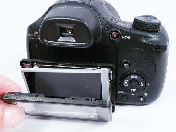
    • Once the plastic housing is separated, disconnect the ribbon wire located on the back of the LCD display. This can be achieved by pulling up lightly on the brown bar that locks the ribbon wire to the circuit board..

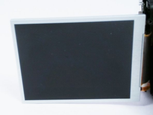
    • Disconnect the remaining two ribbon wires the same way. They are located on the right, rear side of the LCD frame.

  11. この手順は未翻訳です。 翻訳を手伝う。

    : 手順 11、 1の画像 1
    • Using a small Phillips head screwdriver, remove the last 2 cm screw that mounts the circuit board to the metal LCD display frame.

  12. この手順は未翻訳です。 翻訳を手伝う。

    : 手順 12、 2の画像 1 : 手順 12、 2の画像 2
    • Once the circuit board is removed the replacement parts can be installed in the reverse order.

ゴール

2 の人々がこのガイドを完成させました。

作成者

8人の作成者と共同で作成されました。

Elizabeth Surface

メンバー登録日: 08/26/15

1,465 ポイント

9のガイドは作成済み

チーム

USF Tampa, Team 4-6, Meier Fall 2015 USF Tampa, Team 4-6, Meier Fall 2015人のメンバー

USFT-MEIER-F15S4G6

4 メンバー

18のガイドは作成済み

3 件のコメント

my screen is working but in negative effect, any ideas??

wilmer - 返信

Comment réparer la carte circuit imprimé de l'écran? Il y'a un transistor qui reçoit 3.7v et qui laisse rien sortir

Abdoul Traore - 返信

my screen was showing vertical red and green lines but you could read the settings. Now the lcd screen is white. Can the lcd be replaced?

yuclin - 返信

コメントを追加

統計データ:

過去 24時間: 3

過去 7 日: 13

過去 30 日: 35

今までの合計 4,275