はじめに
This guide will demonstrate how to replace the Auxiliary Input, located in the back of the device. There is soldering required, so if you need assistant please read this soldering technique page.
必要な工具と部品
-
-
Gently position the device so that the buttons and speakers lie face down.
-
Unplug the power cord from the "DC Input."
-
-
-
Remove the four 12mm phillips head #2 screws located along the outer edge of the white case.
-
Once you remove the screws, pick the device up so that the grey label on the bottom of the device faces toward you.
-
With your thumbs on either side of the grey label, slowly push with both thumbs until the case pops open.
-
-
-
Grip both sides of the top round part of the case and carefully open it like a clam. The bottom of the two halves are connected by the speaker wire. Do not separate by more than 1 centimeter.
-
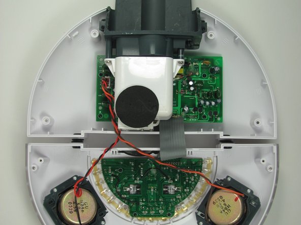
Grip either side of the top round part of the case and carefully open the device to reveal all the hidden treasures inside!
-
Lay the device down, so that all the internal components are facing upwards.
-
-
-
-
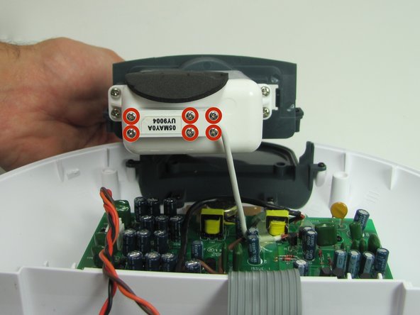
Turn the device over so that the internals are facing down; the Light Intensity Dial will be facing you.
-
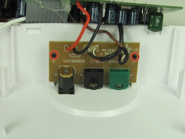
Remove the three 7mm Phillips #1 screws connecting the Zipconnect unit.
-
-
-
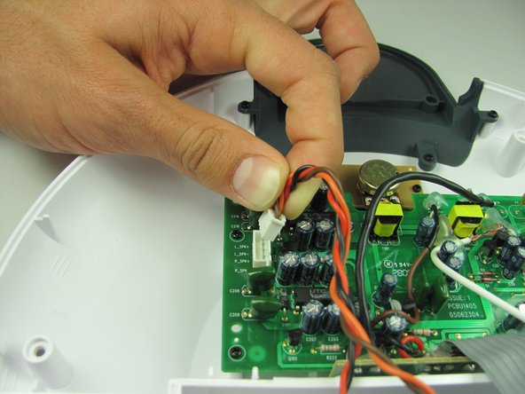
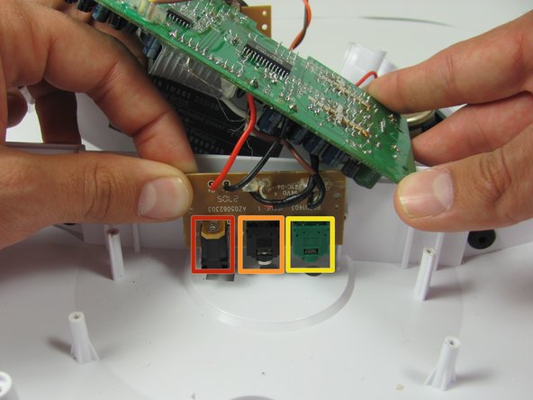
Lift up the circuit board containing the Auxillary, DC, and sub inputs and move the lower case out of the way.
-
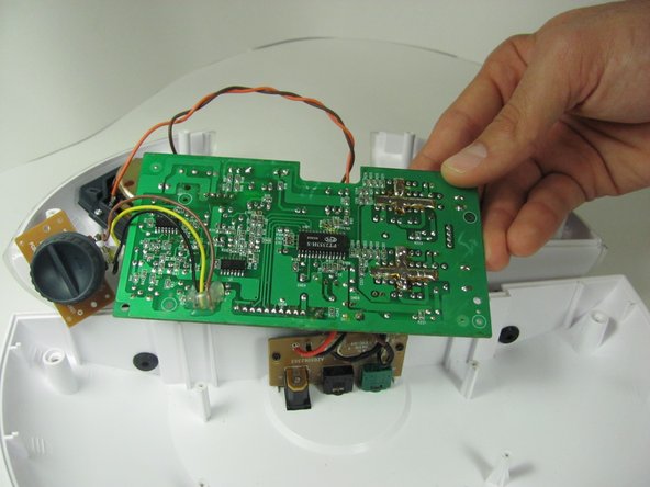
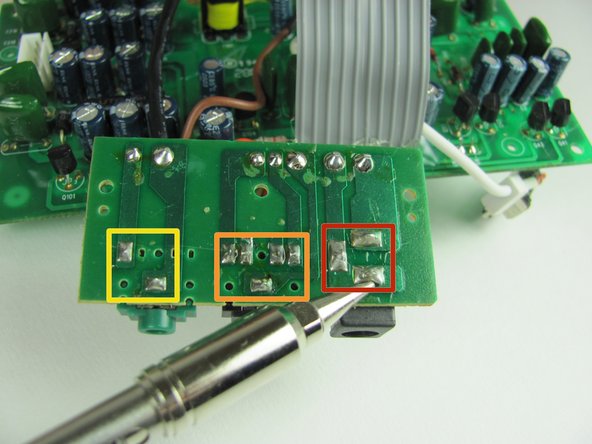
Turn the circuit board over so the solder is visible. Depending on which input is broken remove the solder connecting either the Auxillary, DC, or Sub input.
-
DC input
-
Auxillary Input
-
Sub Input
-


To reassemble your device, follow these instructions in reverse order.
To reassemble your device, follow these instructions in reverse order.
チーム

Cal Poly, Team 11-33, Amido Fall 2013 Cal Poly, Team 11-33, Amido Fall 2013人のメンバー
CPSU-AMIDO-F13S11G33
4 メンバー
8のガイドは作成済み