メインコンテンツにスキップ

このバージョンは誤った内容を含んでいる可能性があります。最新の承認済みスナップショットに切り替えてください。

必要な工具と部品

  1. この手順は未翻訳です。 翻訳を手伝う。

    : 手順 1、 1の画像 1
    • Pry up the small black piece of plastic located between the volume [-] button and the HOLD/ON button.

  2. この手順は未翻訳です。 翻訳を手伝う。

    : 手順 2、 1の画像 1
    • Underneath the piece of plastic you just removed, there is a small screw (Phillips #000, 2.0 mm long). Use a Phillips #000 screwdriver to remove it.

  3. この手順は未翻訳です。 翻訳を手伝う。

    : 手順 3、 2の画像 1 : 手順 3、 2の画像 2
    • Push on the backplate with both thumbs, sliding it towards the top of the device.

    • Once it begins to move, lift up slightly. You can then slide the backplate all the way off.

  4. この手順は未翻訳です。 翻訳を手伝う。

    : 手順 4、 3の画像 1 : 手順 4、 3の画像 2 : 手順 4、 3の画像 3
    • Before removing the circuit board, we must remove the ribbon-like wires attached to two sides of the circuit board.

    • There are two screws (Phillips #000, 2.0 mm long) holding in the circuit board. Use a Phillips #000 screwdriver to take out those screws.

  5. この手順は未翻訳です。 翻訳を手伝う。

    : 手順 5、 2の画像 1 : 手順 5、 2の画像 2
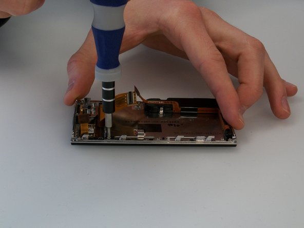
    • The battery is also attached to the circuit board by a cable. The cable is difficult to disconnect with both components in place. It's best to lift the circuit board out partially to give yourself more room to disconnect the connector.

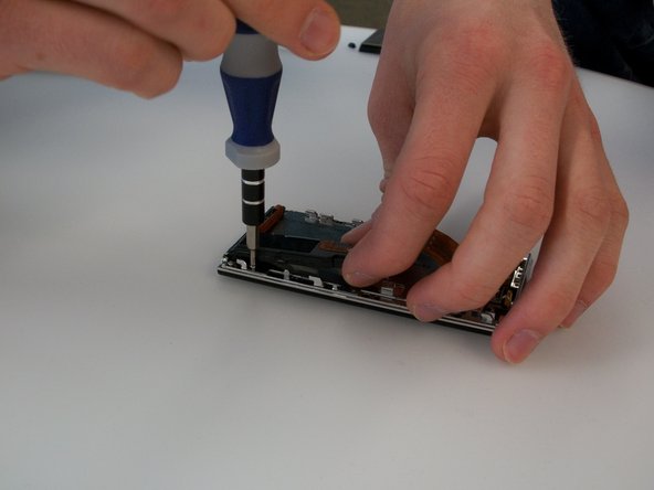
    • The wire that is connected to the circuit board is connected by a plastic piece with two metal prongs.

    • Use the pointy end of the spudger to place in between the computer board and the plastic piece and gently pry the prongs away from the circuit board.

  6. この手順は未翻訳です。 翻訳を手伝う。

    : 手順 6、 1の画像 1
    • Disconnect the battery connector, and then lift the circuit board up.

  7. この手順は未翻訳です。 翻訳を手伝う。

    : 手順 7、 1の画像 1
    • Finally, disconnect the ribbon cable on the bottom of the circuit board. You can then lift the circuit board all the way out.

  8. この手順は未翻訳です。 翻訳を手伝う。

    : 手順 8、 1の画像 1
    • Use the spudger to carefully pry up the battery. The battery is attached with a few spots of glue, so it may not move at first.

  9. この手順は未翻訳です。 翻訳を手伝う。

    : 手順 9、 3の画像 1 : 手順 9、 3の画像 2 : 手順 9、 3の画像 3
    • Remove the six screws (Phillips #000, 2.3 mm long) holding the screen frame to the front of the case. As the picture shows, one of them is hidden under the black speaker/rumble assembly.

  10. この手順は未翻訳です。 翻訳を手伝う。

    : 手順 10、 2の画像 1 : 手順 10、 2の画像 2
    • To access the screw under the black speaker rumble/assembly, you will need to pry the assembly up slightly using the spudger.

    • The assembly is glued to the back of the screen, so the assembly may not move at first. Be patient and careful. Do not pry too hard, or you may break the assembly.

  11. この手順は未翻訳です。 翻訳を手伝う。

    : 手順 11、 1の画像 1
    • Lift the screen out from the case.

ゴール

2 の人々がこのガイドを完成させました。

作成者

2人の作成者と共同で作成されました。

Andrew Groeneveld

メンバー登録日: 02/24/14

567 ポイント

4のガイドは作成済み

チーム

Michigan Tech, Team 5-3, Lauer Spring 2014 Michigan Tech, Team 5-3, Lauer Spring 2014人のメンバー

MTU-LAUER-S14S5G3

4 メンバー

6のガイドは作成済み

2 件のコメント

Hello, excellent instructions , great pictures only want to know if is possible to find the part ?? I mean Samsung doesnt sell the touch screen part in that case where to find it ?? because without the part the instructions are not worthy,,, sorry and thanks.

jo ca - 返信

Very helpful guide. Do you have a manufacturer and part number for the touch screen?

Mark Garvin - 返信

コメントを追加

統計データ:

過去 24時間: 1

過去 7 日: 19

過去 30 日: 39

今までの合計 7,628