はじめに
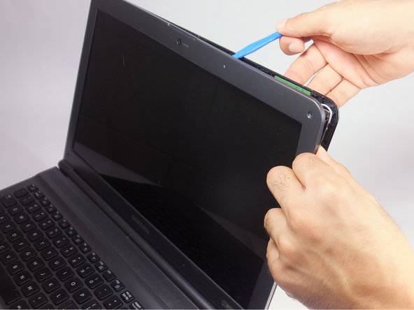
Screen replacement may need to be done when the screen is damaged, such as lines on the screen and not showing anything. Refer to the Troubleshooting page to see more information about this. This guide will display the steps needed to replace a damaged screen on Samsung RC512.
必要な工具と部品
-
-
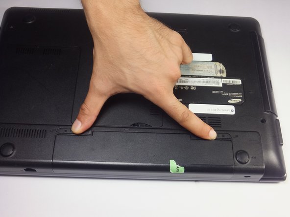
Slide both battery locking notches to either side to remove the battery.
-
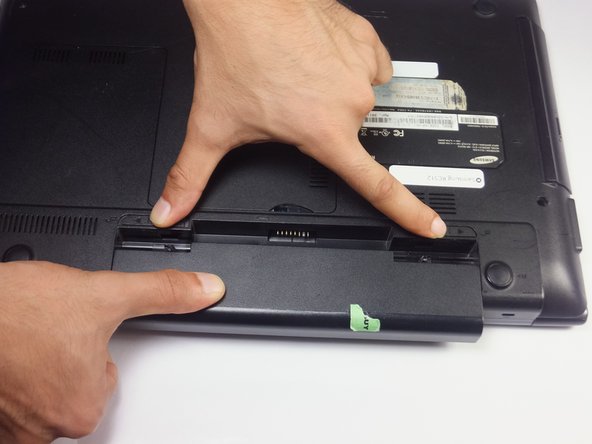
Pull the battery out.
-
-


To reassemble your device, follow these instructions in reverse order.
To reassemble your device, follow these instructions in reverse order.
ある他の人がこのガイドを完成しました。
チーム

USF Tampa, Team 18-2, Blackwell Fall 2016 USF Tampa, Team 18-2, Blackwell Fall 2016人のメンバー
USFT-BLACKWELL-F16S18G2
4 メンバー
8のガイドは作成済み