メインコンテンツにスキップ

このバージョンは誤った内容を含んでいる可能性があります。最新の承認済みスナップショットに切り替えてください。

必要な工具と部品

  1. , 背面ケース: 手順 1、 2の画像 1 , 背面ケース: 手順 1、 2の画像 2
    • プラスチック製の開口ツールや指の爪を使って、電源ボタン付近の背面カメラの左側から差し込みこじ開けます。

  2. : 手順 2、 3の画像 1 : 手順 2、 3の画像 2 : 手順 2、 3の画像 3
    • ツールを差し込んだコーナー付近から背面ケースを持ち上げて、本体から取り出します。

  3. , MicroSD カード: 手順 3、 3の画像 1 , MicroSD カード: 手順 3、 3の画像 2 , MicroSD カード: 手順 3、 3の画像 3
    • スパッジャーの平面側先端や指の爪を使って、カッチと音がするまでMicroSDカードを内側深くまで押します。

    • カチッと音がしたら作業をやめてください。カードがスロットから出てきます。

    • MicroSDカードを取り出します。

    • 再組み立ての際は、元の位置に戻すためMicroSDカードをスロットに 押し込みます。

  4. , バッテリー: 手順 4、 3の画像 1 , バッテリー: 手順 4、 3の画像 2 , バッテリー: 手順 4、 3の画像 3
    • プラスチック製の開口ツールや指の爪をバッテリーコンパートメントの溝に差し込み、上向きにバッテリーを押し上げます。

    • iPhoneからバッテリーを取り出します。

  5. , SIMカード: 手順 5、 3の画像 1 , SIMカード: 手順 5、 3の画像 2 , SIMカード: 手順 5、 3の画像 3
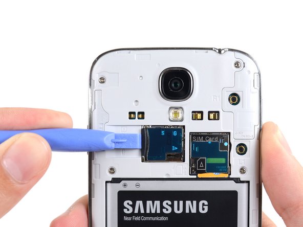
    • プラスチック製の開口ツールや指の爪を使って、SIMカードを奥まで軽くおします。カチッという音が鳴ったら止めてください。

    • カードから手を離すとスロットからカードが出てきます。

    • SIMカードを取り出します。

    • 再組み立ての際は、SIMカードがカッチと音がして定位置に装着されるまでスロットの中に押し込みます。

  6. , ミッドフレーム: 手順 6、 1の画像 1
    • ディスプレイアセンブリに留められたミッドフレームから 4.0 mm #00プラスネジを9本外します。

  7. : 手順 7、 2の画像 1 : 手順 7、 2の画像 2
    • ミッドフレームはミッドフレームのクロムベゼルの裏側に、ディスプレイアセンブリに幾つかのプラスチッククリップで止められています。

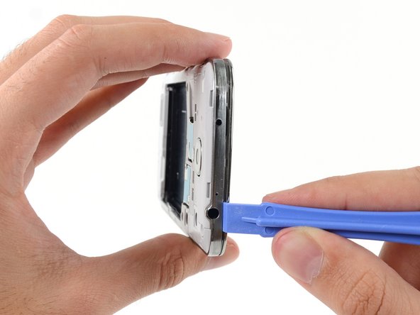
    • デバイス本体サイドにある音量ボタン側から作業を始めます。ディスプレイガラス周辺のクロムベゼルと大きなクロムの淵部分の間にプラスチック製の開口ツールを差し込みます。この両側の繋ぎ目を探してください。

    • 開口ツールを繋ぎ目にそってスライドします。進みながらプラスチッククリップを外します。

    • こじ開ける作業は大変丁寧に作業を進めてください。一方で、プラスチッククリップを軽く外す程度にします。クリップを大きく曲げてしまうと、ミッドフレームのベゼルにある幾つかの薄いポイントが割れてしまうことがありますのでご注意ください。

  8. : 手順 8、 2の画像 1 : 手順 8、 2の画像 2
    • 本体の角周辺も続けてこじ開けます。

    • 開口ツールをミッドフレームとデバイスの底側のディスプレイの間の繋ぎ目に沿ってスライドさせ、プラスチックのクリップを外していきます。

  9. : 手順 9、 2の画像 1 : 手順 9、 2の画像 2
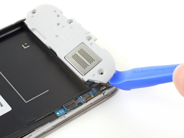
    • 再び、電源ボタン側の角周辺をこじ開けます。

    • 開口ツールを繋ぎ目に沿ってスライドします。

  10. : 手順 10、 2の画像 1 : 手順 10、 2の画像 2
    • 開口ツールをデバイス本体上部周辺でスライドさせながらクリップの残りを外し、ディスプレイアセンブリからミッドフレームを外します。

    • この時点で、再びプラスチックの開口ツールをデバイスの全周辺に沿ってスライドさせます。プラスチックのクリップを全て外したか確認します。

  11. : 手順 11、 3の画像 1 : 手順 11、 3の画像 2 : 手順 11、 3の画像 3
    • ディスプレイアセンブリからミッドフレームを取り出します。

  12. , マザーボードアセンブリ: 手順 12、 3の画像 1 , マザーボードアセンブリ: 手順 12、 3の画像 2 , マザーボードアセンブリ: 手順 12、 3の画像 3
    • スパッジャーの平面側先端を使って、USBボードコネクターの接続を外します。

    • 正面カメラケーブルのコネクターの接続を外します。

    • イヤホンスピーカーのアセンブリケーブルコネクターの接続を外します。

  13. : 手順 13、 3の画像 1 : 手順 13、 3の画像 2 : 手順 13、 3の画像 3
    • ヘッドホンジャックアセンブリのケーブルコネクターの接続を外します。

    • ディスプレイ/デジタイザーケーブルコネクターの接続を外します。

    • アンテナケーブルコネクターの接続を外します。

  14. : 手順 14、 1の画像 1
    • マザーボードアセンブリから2.4 mm #00プラスネジを1本外します。

  15. : 手順 15、 2の画像 1 : 手順 15、 2の画像 2
    • 丁寧にマザーボードを取り出します。

    • ESDダメージを防ぐため、マザーボードの端を押さえてください。ディスプレイアセンブリからマザーボードを取り出す際に、ケーブルを絡めないようご注意ください。

  16. この手順は未翻訳です。 翻訳を手伝う。

    : 手順 16、 2の画像 1 : 手順 16、 2の画像 2
    • Use an opening tool to unclip the speaker assembly on the bottom of the phone.

    • Remove the speaker assembly.

  17. この手順は未翻訳です。 翻訳を手伝う。

    : 手順 17、 2の画像 1 : 手順 17、 2の画像 2
    この手順で使用する道具:
    Tweezers
    $4.99
    購入する
    • Use tweezers to lift and de-route the antenna cable from the edge of the case.

  18. この手順は未翻訳です。 翻訳を手伝う。

    : 手順 18、 2の画像 1 : 手順 18、 2の画像 2
    • Lift directly up on the antenna connection to remove it from the speaker daughter board.

    • Completely remove the antenna cable.

  19. この手順は未翻訳です。 翻訳を手伝う。

    : 手順 19、 1の画像 1
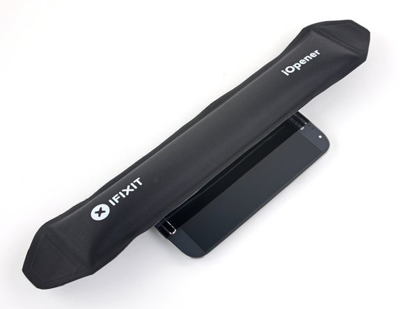
    • Prepare an iOpener (or use a hair dryer or heat gun) and heat the screen side of the phone to loosen the display adhesive.

    • Leave the iOpener on the phone for at least two minutes to fully heat the screen and soften the adhesive holding it to the case.

    • You may need to reheat the iOpener and repeat this procedure several times until the display adhesive gets loose enough.

  20. この手順は未翻訳です。 翻訳を手伝う。

    : 手順 20、 2の画像 1 : 手順 20、 2の画像 2
    この手順で使用する道具:
    Jimmy
    $7.95
    購入する
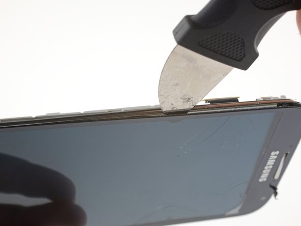
    • Because the gap between the screen and phone frame is so thin, a Jimmy is needed to separate the two. Read the following warnings carefully before proceeding.

    • Even though the metal blade is mostly dull, be careful not to apply too much pressure, as this might cause the Jimmy to slip and cut you or damage the phone.

    • Wear eye protection. The glass may break, sending pieces flying.

  21. この手順は未翻訳です。 翻訳を手伝う。

    : 手順 21、 3の画像 1 : 手順 21、 3の画像 2 : 手順 21、 3の画像 3
    • With the adhesive lose, insert the blade into the small gap between the frame and the screen, near the volume rocker.

    • Slowly slide the blade down the length of the phone towards the charge port to release the screen glass from the LCD.

    • The glass will most likely develop hairline fractures as you bend it during this step. Make sure you have proper eye protection.

  22. この手順は未翻訳です。 翻訳を手伝う。

    : 手順 22、 2の画像 1 : 手順 22、 2の画像 2
    • The next three steps involve removing extremely fragile components. Consider working on a surface that will be easy to clean up afterwards.

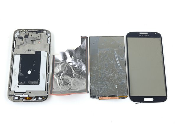
    • With the screen glass completely loosened around the edges, remove it from the phone.

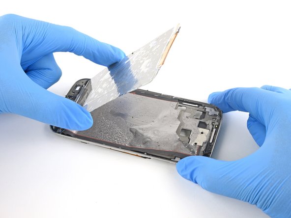
    • The fragile LCD display underneath the glass has a tendency to shatter into small pieces. If in doubt, protect your hands with gloves.

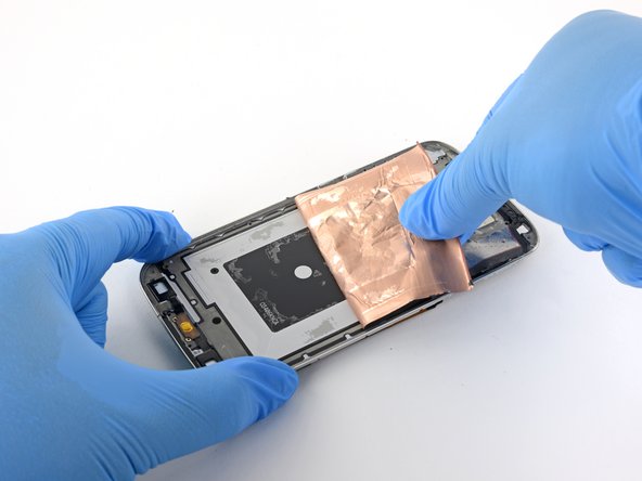
    • Cover the LCD with tape to prevent the broken glass from spreading or falling out during removal.

  23. この手順は未翻訳です。 翻訳を手伝う。

    : 手順 23、 2の画像 1 : 手順 23、 2の画像 2
    • Carefully peel the cracked LCD away from the frame.

    • If necessary, push the Jimmy between the LCD and the frame to loosen it from the adhesive.

    • Remove the LCD.

  24. この手順は未翻訳です。 翻訳を手伝う。

    : 手順 24、 2の画像 1 : 手順 24、 2の画像 2
    • Grab the foil liner underneath the LCD and peel it away from the case.

    • You may need to reheat and reapply the iOpener to help loosen the adhesive.

  25. この手順は未翻訳です。 翻訳を手伝う。

    : 手順 25、 3の画像 1 : 手順 25、 3の画像 2 : 手順 25、 3の画像 3
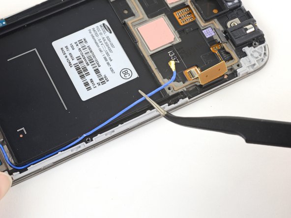
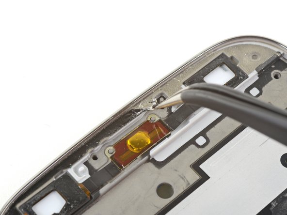
    • Use tweezers to remove all old adhesive from the phone case before installing the new display.

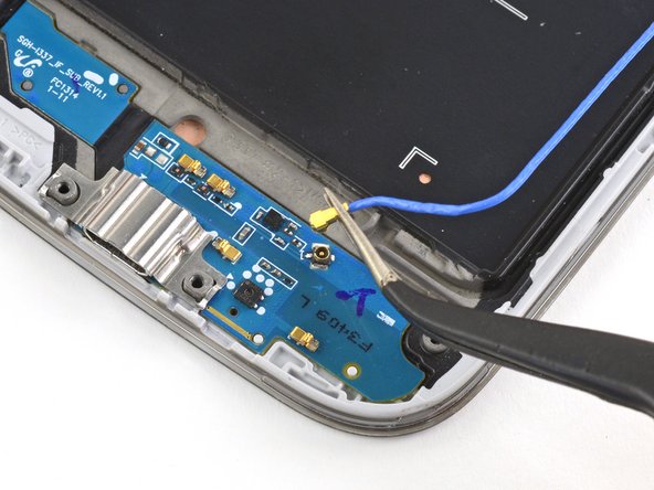
    • When you install the replacement display, feed the display cable through the hole on the rear of the case.

ゴール

27 の人々がこのガイドを完成させました。

作成者

5人の作成者と共同で作成されました。

Carsten Frauenheim

メンバー登録日: 03/10/20

114,422 ポイント

338のガイドは作成済み

チーム

iFixit iFixit人のメンバー

Staff

135 メンバー

17,269のガイドは作成済み

0 件のコメント

コメントを追加

統計データ:

過去 24時間: 2

過去 7 日: 10

過去 30 日: 51

今までの合計 30,782