メインコンテンツにスキップ

このバージョンは誤った内容を含んでいる可能性があります。最新の承認済みスナップショットに切り替えてください。

必要な工具と部品

  1. , Samsung Galaxy A51 SIMトレイの取り外し: 手順 1、 3の画像 1 , Samsung Galaxy A51 SIMトレイの取り外し: 手順 1、 3の画像 2 , Samsung Galaxy A51 SIMトレイの取り外し: 手順 1、 3の画像 3
    • SIMカードを取り外すイジェクトツール、SIMイジェクトビット、またはまっすぐ伸ばしたクリップを、デバイス本体左側にあるSIMトレイの穴に挿入してください。

    • 強く押すと、トレイが排出されます。

    • SIMカードトレイを取り外します。

    • カードを再挿入する際は、トレイの向きを間違えないようにしてください。

  2. この手順は未翻訳です。 翻訳を手伝う。

    : 手順 2、 1の画像 1
    • Before beginning this procedure, completely power off your phone.

    • Prepare an iOpener and apply it to the back cover to soften the adhesive.

    • The adhesive of the Samsung Galaxy A51 is very strong. You can use a hair dryer or a heat gun if you aren't able to open the device with the iOpener.

    • Be careful not to overheat the phone—the AMOLED display and internal battery are both susceptible to heat damage.

  3. この手順は未翻訳です。 翻訳を手伝う。

    : 手順 3、 3の画像 1 : 手順 3、 3の画像 2 : 手順 3、 3の画像 3
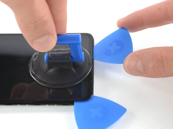
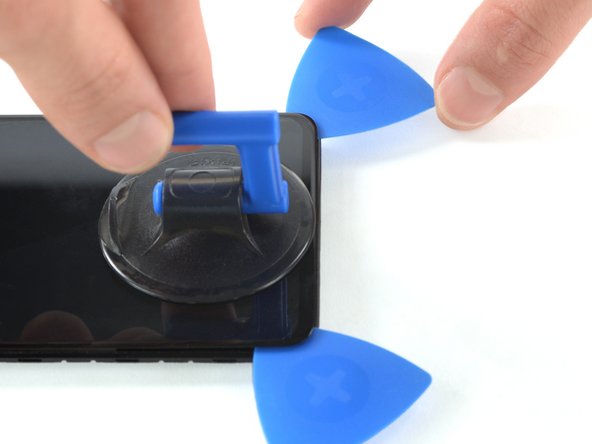
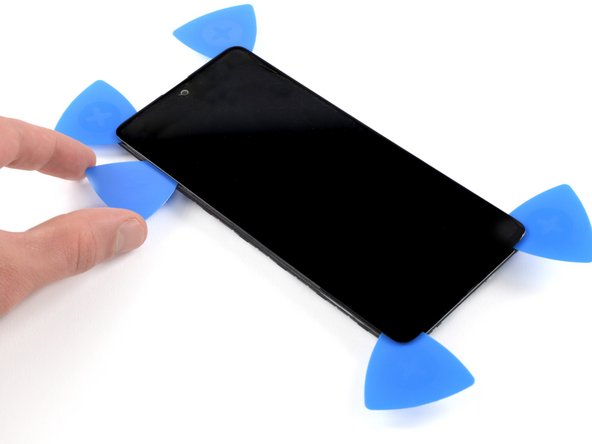
    • Insert the tip of an opening pick between the frame and the back cover at the bottom of the phone near the USB-C port.

    • If you can't get between the back cover and midframe with your opening pick, you can use a suction handle or strong tape to pull up the back cover to create a gap.

    • Slide the opening pick to the bottom right corner and leave it there.

  4. この手順は未翻訳です。 翻訳を手伝う。

    : 手順 4、 3の画像 1 : 手順 4、 3の画像 2 : 手順 4、 3の画像 3
    • Insert a second opening pick and slide it from the bottom right corner to the bottom left corner to cut the adhesive.

    • Leave the opening picks in place to prevent the adhesive from resealing.

  5. この手順は未翻訳です。 翻訳を手伝う。

    : 手順 5、 3の画像 1 : 手順 5、 3の画像 2 : 手順 5、 3の画像 3
    • Insert a third opening pick under the bottom left corner of the back cover.

    • If you have any trouble, apply more heat to further soften the adhesive. Follow the iOpener instructions to avoid overheating.

    • Slide the opening pick along the left edge of the phone.

    • Leave the opening pick in the top left corner to prevent the adhesive from resealing.

  6. この手順は未翻訳です。 翻訳を手伝う。

    : 手順 6、 3の画像 1 : 手順 6、 3の画像 2 : 手順 6、 3の画像 3
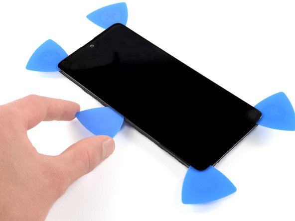
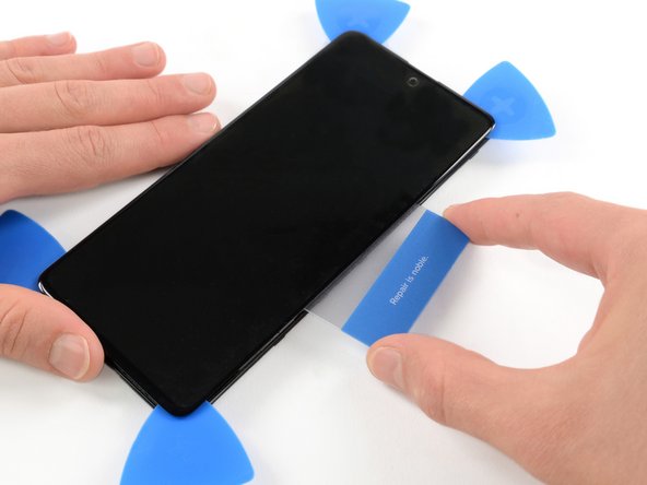
    • Insert a fourth opening pick under the top left corner of the back cover near the camera.

    • Slide the tip of the opening pick along the top edge of the phone to the right corner to cut the adhesive.

    • Leave the opening pick in the top right corner to prevent the adhesive from resealing.

  7. この手順は未翻訳です。 翻訳を手伝う。

    : 手順 7、 3の画像 1 : 手順 7、 3の画像 2 : 手順 7、 3の画像 3
    • With opening picks in all four corners, insert a fifth and final opening pick under the top right corner of the back cover.

    • Slide the tip of the opening pick along the right edge of the phone to the bottom right corner to cut the remaining adhesive.

  8. この手順は未翻訳です。 翻訳を手伝う。

    : 手順 8、 1の画像 1
    • Remove the back cover.

    • After installing the back cover, apply strong, steady pressure to your phone for several minutes to help the adhesive form a good bond—a stack of heavy books works well.

  9. , ディスプレイ: 手順 9、 2の画像 1 , ディスプレイ: 手順 9、 2の画像 2
    • スパッジャーの平面側を使って、スマートフォン底面に搭載されたディスプレイを固定しているケーブルをこじ開け、接続を外します。

  10. : 手順 10、 1の画像 1
    • 温めたiOpenerを用意し、ディスプレイに2分以上当てて、下に留められた粘着剤を温めて柔らかくします。

    • 粘着剤を切開ためにスマートフォンを十分に温めます。iOpenerを何度かにわたって再加熱して温める必要があります。過熱を避けるため、iOpenerの説明書に従ってください。

  11. : 手順 11、 3の画像 1 : 手順 11、 3の画像 2 : 手順 11、 3の画像 3
    • スクリーンが熱くて触れない程度まで温まったら、スマートフォン上部の縁に吸盤カップを装着します。

    • スクリーンがひび割れている場合、吸盤が上手く装着しないことがあります。強力なテープで持ち上げてみたり、瞬間接着剤で吸盤を固定し、硬化させると上手くいきます。

    • 隙間にオープニングピックを差し込み、右上にスライドさせて接着剤を切り始めます。

  12. : 手順 12、 3の画像 1 : 手順 12、 3の画像 2 : 手順 12、 3の画像 3
    • 2つ目のピックを挿入し、左上にスライドさせます。

    • 接着剤の再付着を防ぐため、開口部のピックをそのままにしておきます。

  13. : 手順 13、 3の画像 1 : 手順 13、 3の画像 2 : 手順 13、 3の画像 3
    • 3枚目のオープニングピックを差し込み、左端に沿ってスライドさせて粘着剤をカットします。

    • 接着剤の再付着を防ぐため、左下隅の開口部にオープニングピックを残してください。

  14. : 手順 14、 3の画像 1 : 手順 14、 3の画像 2 : 手順 14、 3の画像 3
    • 4枚目のオープニングピックを左下コーナーに挿入し、右下隅へス向けてライドさせます。

    • 接着剤の再付着を防ぐため、オープニングピックをそのままにしておきます。

  15. : 手順 15、 3の画像 1 : 手順 15、 3の画像 2 : 手順 15、 3の画像 3
    • 5枚目のオープニングピックを差し込み、デバイス左端に沿ってスライドさせながら、残りの接着剤をカットします。

  16. : 手順 16、 2の画像 1 : 手順 16、 2の画像 2
    • 加熱したiOpenerを再度フレームに当て、下に留められた接着剤を柔らかくします。

    • スクリーン下に留められている長方形の接着剤に注意しながら、温まるまで待ってください。

  17. : 手順 17、 3の画像 1 : 手順 17、 3の画像 2 : 手順 17、 3の画像 3
    • ディスプレイと本体左側端に出来た隙間に、プラスチックカードを挿入します。

    • プラスチックカードを押し込んで、接着剤全体が切り開くまで前後にスライドします。

    • 接着剤全体を切開したことを確認したら、四隅にあるオープニングピックを外します。

    • まだスクリーンを完全に取り外さないでください。ディスプレイケーブルはまだフレームに繋がったままの状態です。

  18. : 手順 18、 3の画像 1 : 手順 18、 3の画像 2 : 手順 18、 3の画像 3
    • ディスプレイケーブルを慎重にフレームに通して解放します。

  19. : 手順 19、 3の画像 1 : 手順 19、 3の画像 2 : 手順 19、 3の画像 3
    • ディスプレイをを取り外します。

  20. この手順は未翻訳です。 翻訳を手伝う。

    : 手順 20、 1の画像 1
    • Débrancher le connecteur d’antenne en bas à droite

  21. この手順は未翻訳です。 翻訳を手伝う。

    : 手順 21、 1の画像 1
    • Utilisez une spatule pour débrancher le connecteur au PCB principal, sur la face arrière du PCB.

  22. この手順は未翻訳です。 翻訳を手伝う。

    : 手順 22、 1の画像 1
    • En utilisant une spatule plate, décoller le micro de son compartiment.

    • Attention au flex qui est assez fin

  23. この手順は未翻訳です。 翻訳を手伝う。

    : 手順 23、 1の画像 1
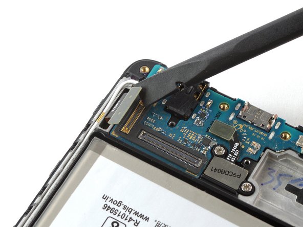
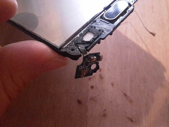
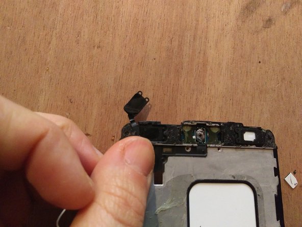
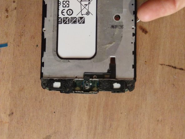
    • Décollez le PCB de son compartiment et le soulever vers l’autre côté, sans tirer.

    • Procédez élément par élement, pour ne pas endommager les parties flex. De mon côté je n’ai pas réussi et j’ai déchiré le flex autour du port jack...

    • Faites également attention aux deux flex qui relient aux boutons, situés d’une part et d’autre du PCB (entourés en rouge sur la photo)

  24. この手順は未翻訳です。 翻訳を手伝う。

    : 手順 24、 2の画像 1 : 手順 24、 2の画像 2
    • Enlever ou soulever la vitre de l’autre côté du téléphone.

    • Décoller les contacts des boutons.

  25. この手順は未翻訳です。 翻訳を手伝う。

    : 手順 25、 1の画像 1
    • Cette vue montre la carte de remplacement en entier

    • Notez les parties flexibles, entourées en jaunes : ce sont les parties les plus fragiles du PCB.

  26. この手順は未翻訳です。 翻訳を手伝う。

    : 手順 26、 1の画像 1
    • Placer la carte de remplacement dans son emplacement

    • Rebrancher le connecteur au PCB principal, situé au verso de la carte

  27. この手順は未翻訳です。 翻訳を手伝う。

    : 手順 27、 3の画像 1 : 手順 27、 3の画像 2 : 手順 27、 3の画像 3
    • Enlever les stickers autocollants de la nouvelle carte

    • Enlever l’ancien sticker filtrant blanc sous le bouton

    • Coller les deux éléments de rétroéclairage bouton dans leurs emplacements

  28. この手順は未翻訳です。 翻訳を手伝う。

    : 手順 28、 1の画像 1
    • Rebrancher le connecteur d’antenne

  29. この手順は未翻訳です。 翻訳を手伝う。

    : 手順 29、 1の画像 1
    • À ce stade, il y a 17 vis à remonter à l’arrière du téléphone

    • Recoller l’écran et le cache arrière

ゴール

3 の人々がこのガイドを完成させました。

作成者

1人の作成者と共同作成されました。

Eve Redero

メンバー登録日: 02/28/22

2,205 ポイント

9のガイドは作成済み

0 件のコメント

コメントを追加

統計データ:

過去 24時間: 9

過去 7 日: 57

過去 30 日: 228

今までの合計 3,196