メインコンテンツにスキップ

Reflowing solder joints on a TEAC GSA-5300 stereo integrated amplifier

必要な工具と部品

  1. Reflowing solder joints on a TEAC GSA-5300 stereo integrated amplifier, Reflowing solder joints on a TEAC GSA-5300 stereo integrated amplifier: 手順 1、 2の画像 1 Reflowing solder joints on a TEAC GSA-5300 stereo integrated amplifier, Reflowing solder joints on a TEAC GSA-5300 stereo integrated amplifier: 手順 1、 2の画像 2
    • I used 1000v insulated electricians screwdrivers, as I like to be safe when working on electronics that have a higher risk of zapping me.

    • Amplifiers can have a high current stored in the large internal capacitors. Even with the insulated screwdrivers, please be sensible and ensure the amplifier is unplugged and try to leave it without power for a day or so. Also, read up on working with capacitors before you start work.

  2. Reflowing solder joints on a TEAC GSA-5300 stereo integrated amplifier: 手順 2、 1の画像 1
    • Turn the amplifier over onto its side and you will find two Phillips #2 screws holding the main black casing on, on each side of the amplifier. Remove them using the Phillips #2 screwdriver.

  3. Reflowing solder joints on a TEAC GSA-5300 stereo integrated amplifier: 手順 3、 3の画像 1 Reflowing solder joints on a TEAC GSA-5300 stereo integrated amplifier: 手順 3、 3の画像 2 Reflowing solder joints on a TEAC GSA-5300 stereo integrated amplifier: 手順 3、 3の画像 3
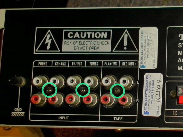
    • Once the main casing is removed, you'll need to remove the back panel. Keep the amplifier on its side and remove the two, Phillips #1 screws holding it on, on both sides of the amplifier.

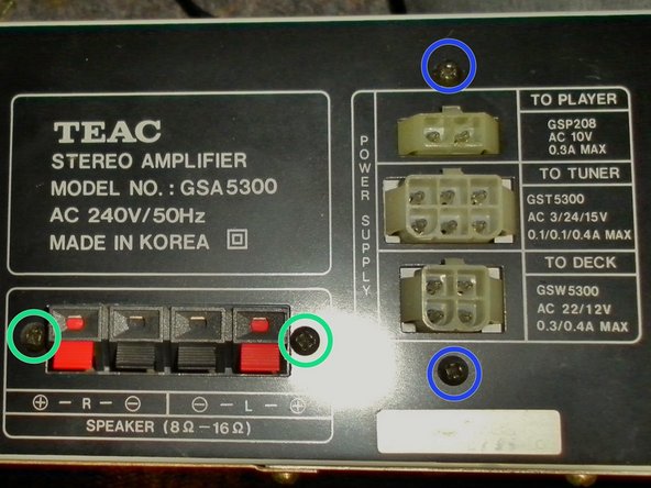
    • You'll also need to turn the amplifier over, and remove 5 additional, Phillips #1 screws from the back of the amplifier.

    • Leave these screws in, as they aren't required to be removed, in order to take the back panel off.

  4. Reflowing solder joints on a TEAC GSA-5300 stereo integrated amplifier: 手順 4、 3の画像 1 Reflowing solder joints on a TEAC GSA-5300 stereo integrated amplifier: 手順 4、 3の画像 2 Reflowing solder joints on a TEAC GSA-5300 stereo integrated amplifier: 手順 4、 3の画像 3
    • Now, to completely remove the back panel and the left hand back service panel, you'll need to remove 5 Phillips #1 screws.

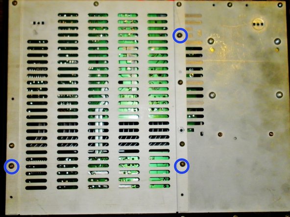
    • To remove the service panel, you need to remove a further 3, Phillips #1 screws. once you have done this, you can remove the back panel and the service panel.

    • Leave these three screw in as the service panel has larges holes for these three screws and undoing them, undoes the circuit boards stand offs.

  5. Reflowing solder joints on a TEAC GSA-5300 stereo integrated amplifier: 手順 5、 1の画像 1
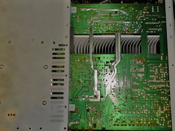
    • Now to get down to the reflowing. Put the tip of the soldering iron, onto each of the solder joins. When they melt (Aprox. 10 seconds using a 30 Watt soldering iron), add a little extra solder to the molten solder pool.

    • Once you have reflowed the solder joins, reassemble the amplifier and connect the speakers etc, to test if it has worked.

    • Don't hold the soldering iron on the circuit broad as you can damage it and the terminal block.

終わりに

To reassemble your device, follow these instructions in reverse order.

8 の人々がこのガイドを完成させました。

作成者

2人の作成者と共同で作成されました。

james

メンバー登録日: 11/29/13

2,213 ポイント

2のガイドは作成済み

チーム

Master Techs Master Techs人のメンバー

Community

322 メンバー

2,506のガイドは作成済み

0 件のコメント

コメントを追加

統計データ:

過去 24時間: 0

過去 7 日: 4

過去 30 日: 19

今までの合計 2,699