はじめに
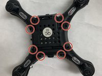
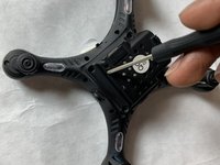
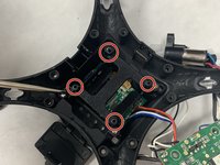
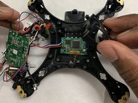
This guide shows how to replace the camera module for the Protocol Videodrone AP Drone. This is a slightly lengthy process as you will have to disassemble most of your drone. The camera module itself is both the sensor housing + the circuit board connected it it. You will only have to replace the circuit board, as the sensor housing is attached to it.
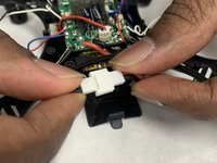
Remember to use the included #0 Phillips screwdriver that came with your drone.
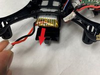
A soldering iron is required, so keep one ready. If you're not experienced with soldering, take a look at this guide for How to Solder and Desolder Connections.
Before you begin, make sure that your drone is turned off and it's unplugged from the charger. You should also remove the battery before you begin.
必要な工具と部品


To reassemble your device, follow these instructions in reverse order.

チーム

IUPUI, Team S2-G2, Harley Fall 2019 IUPUI, Team S2-G2, Harley Fall 2019人のメンバー
IUPUI-HARLEY-F19S2G2
3 メンバー
2のガイドは作成済み