必要な工具と部品
-
-
この手順は未翻訳です。 翻訳を手伝う。
-
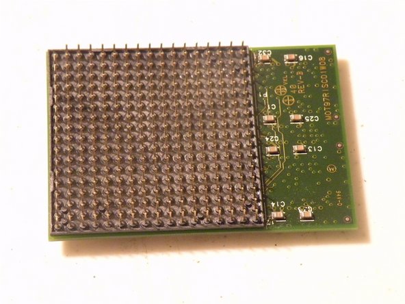
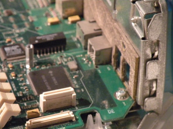
Graphics Card:
-
The Powermac G3 Came Standard With A 16MB ATI 3D Rage PCI Mac Edition Card, there are only a few available upgrade cards.
-
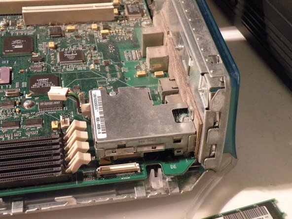
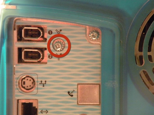
Start By Removing this Screw.
-
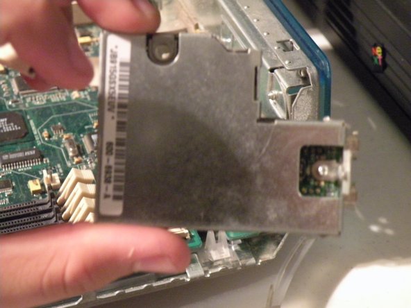
Once that's done, pull the card out.
-
Sorry Guys, Regular PCI Cards Won't work here, only Mac Edition PCI-Compatible Cards, and this card won't work in a PC, Also, graphics cards only work in the first slot, the other 4 PCI Slots won't support graphics cards.
-
-
この手順は未翻訳です。 翻訳を手伝う。
-
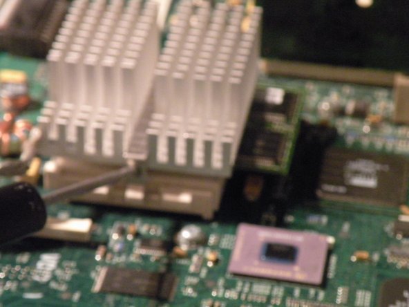
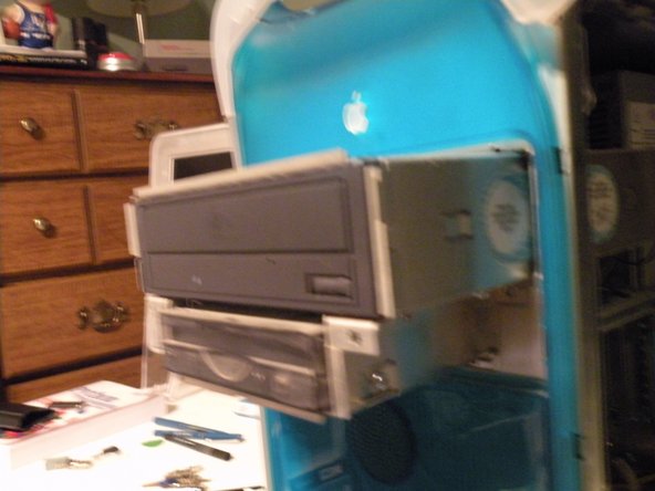
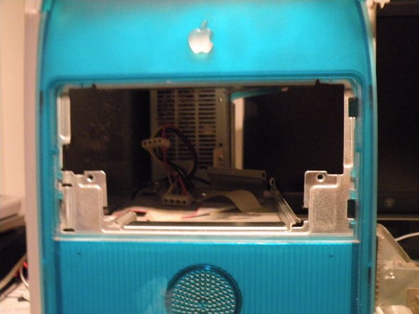
Removing the power supply
-
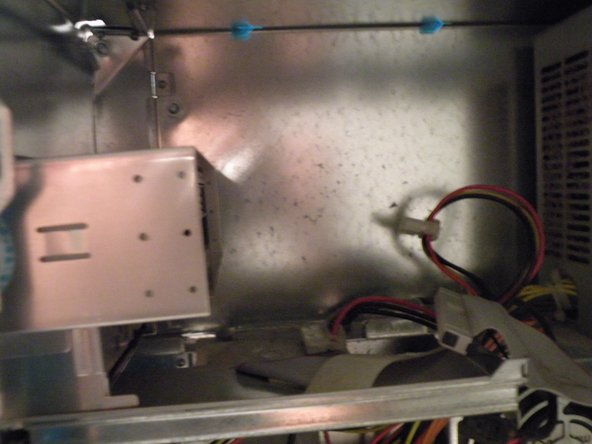
Disconnect the power connector from the logic board (this looks alot like a standard ATX connector. The lone difference is that the wire which supplies -5V on an ATX supply [pin 18] becomes a ground wire in the B&W G3. If you just plug in an ATX supply without any modifications, you'll short out its -5V output. )
-
There is a 4-Pin Cable connected to the front panel box, remove it.
-
Disconnect the internal fan cable.
-
The Fan Connector
-
Then Route all of the cables up through the case to the level of the power supply.
-


チーム

6 件のコメント
I dub thee Chris Green, The Teardown Machine. Good work!
Actually, I have to call you on your comment about the PCI slots. I used to run a dual monitor setup on my B&W G3. I had an ATI Xclaim VR 128 installed in the second slot, giving me a second graphics card, with a TV tuner/AV input. It worked perfectly. The Tuner's software never made the transition to Mac OS X, sadly, so i had to boot into OS 9 any time I wanted to do recording, but it most definitely worked.
Yep, the pci slots will absolutely run graphics cards. If they didn't they wouldn't be pci slots. I also ran graphics cards off of them. However, they run like crud compared to the 66mhz slot, since they are shared and 33mhz. You can also run standard PC graphics cards, as long as there is a mac compatible rom that you can flash onto it. Reflashed cards used to sell on ebay for real good prices.
khlae -
Nice teardown.