メインコンテンツにスキップ

Polyconcept 900-MHz Retro Cordless Telephone Device Motherboard Replacement

必要な工具と部品

  1. Polyconcept 900-MHz Retro Cordless Telephone Device Motherboard Replacement, Removing Power and Telephone Cords: 手順 1、 3の画像 1 Polyconcept 900-MHz Retro Cordless Telephone Device Motherboard Replacement, Removing Power and Telephone Cords: 手順 1、 3の画像 2 Polyconcept 900-MHz Retro Cordless Telephone Device Motherboard Replacement, Removing Power and Telephone Cords: 手順 1、 3の画像 3
    • To disconnect the phone cord, squeeze the tab against the connector and pull the cord away from the telephone-line-in-jack.

    • To disconnect the power cord, grasp the end and pull back and away until it is disconnected.

    • Once disconnected remove each cord from its track.

  2. Polyconcept 900-MHz Retro Cordless Telephone Device Motherboard Replacement, Removing Screws to Base Plate: 手順 2、 1の画像 1
    • Using a Phillips #00 screwdriver, remove the six 7mm screws from the base plate.

  3. Polyconcept 900-MHz Retro Cordless Telephone Device Motherboard Replacement, Remove Bottom Plate from Base: 手順 3、 3の画像 1 Polyconcept 900-MHz Retro Cordless Telephone Device Motherboard Replacement, Remove Bottom Plate from Base: 手順 3、 3の画像 2 Polyconcept 900-MHz Retro Cordless Telephone Device Motherboard Replacement, Remove Bottom Plate from Base: 手順 3、 3の画像 3
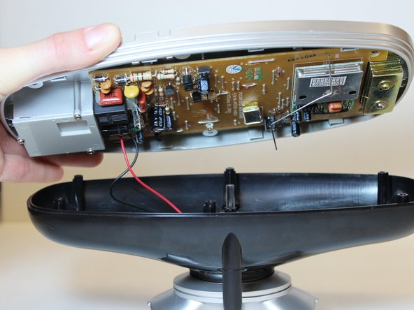
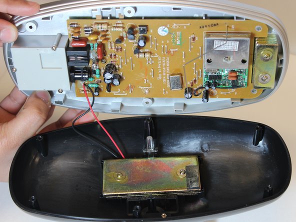
    • With the base turned upside down, grasp the edges of the base plate and gently lift from the rest of the base.

    • Two wires lead from the motherboard to the charger plate, so the two parts cannot be completely separated without further steps.

  4. Polyconcept 900-MHz Retro Cordless Telephone Device Motherboard Replacement, Removing Screws: 手順 4、 1の画像 1
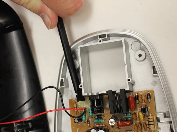
    • Use a Phillips #00 screwdriver to remove the three 6mm screws from the phone and power jack cover plate.

    • Lift the phone and power jack cover plate away from the motherboard.

  5. Polyconcept 900-MHz Retro Cordless Telephone Device Motherboard Replacement, Removing the Motherboard Screw: 手順 5、 1の画像 1
    • Use a Philips #00 screwdriver to remove the single 6mm screw from the motherboard.

  6. Polyconcept 900-MHz Retro Cordless Telephone Device Motherboard Replacement, Removing Glue Covering for Wire Connections: 手順 6、 2の画像 1 Polyconcept 900-MHz Retro Cordless Telephone Device Motherboard Replacement, Removing Glue Covering for Wire Connections: 手順 6、 2の画像 2
    • Use the spudger tool to carefully scrape the glue off of the connection points of both the black and red wires.

  7. Polyconcept 900-MHz Retro Cordless Telephone Device Motherboard Replacement, Desoldering Wire Connections: 手順 7、 1の画像 1
    • Gently lift the motherboard away from the base plate and flip over.

    • Use the soldering station to desolder the wire connections.

    • For further instructions on using the soldering station click here.

終わりに

To reassemble your device, follow these instructions in reverse order.

作成者

3人の作成者と共同で作成されました。

Jay Gunter

メンバー登録日: 10/27/14

378 ポイント

3のガイドは作成済み

チーム

Eastern Washington University, Team 1-1, Carnegie Fall 2014 Eastern Washington University, Team 1-1, Carnegie Fall 2014人のメンバー

EWU-CARNEGIE-F14S1G1

6 メンバー

12のガイドは作成済み

0 件のコメント

コメントを追加

統計データ:

過去 24時間: 1

過去 7 日: 6

過去 30 日: 12

今までの合計 373