メインコンテンツにスキップ

このバージョンは誤った内容を含んでいる可能性があります。最新の承認済みスナップショットに切り替えてください。

必要な工具と部品

  1. この手順は未翻訳です。 翻訳を手伝う。

    : 手順 1、 2の画像 1 : 手順 1、 2の画像 2
    • Turn the controller over and unscrew the four 10mm screws with a PH #00 screwdriver.

  2. この手順は未翻訳です。 翻訳を手伝う。

    : 手順 2、 3の画像 1 : 手順 2、 3の画像 2 : 手順 2、 3の画像 3
    • Pinch the sides of the back panel to remove it and set it aside.

  3. この手順は未翻訳です。 翻訳を手伝う。

    : 手順 3、 2の画像 1 : 手順 3、 2の画像 2
    • Hold the base of the controller with one hand and with the other carefully pull up on the white spherical piece to remove it.

  4. この手順は未翻訳です。 翻訳を手伝う。

    : 手順 4、 2の画像 1 : 手順 4、 2の画像 2
    • Push the Lithium Ion battery from its slot to remove it.

    • Be mindful not to damage the wires or wired components, as the battery will still be attached via its connector.

  5. この手順は未翻訳です。 翻訳を手伝う。

    : 手順 5、 1の画像 1
    • Unscrew the 9mm screw in the battery slot with a PH #00 screwdriver.

  6. この手順は未翻訳です。 翻訳を手伝う。

    : 手順 6、 2の画像 1 : 手順 6、 2の画像 2
    • Using a plastic opening tool, carefully pry the rumble motor free.

  7. この手順は未翻訳です。 翻訳を手伝う。

    : 手順 7、 1の画像 1
    • Unscrew the 9mm screw behind the rumble motor slot with a PH #00 screwdriver.

  8. この手順は未翻訳です。 翻訳を手伝う。

    : 手順 8、 3の画像 1 : 手順 8、 3の画像 2 : 手順 8、 3の画像 3
    • Carefully pinch the plastic sides of the battery slot and lift it (along with the circuit board) from the plastic shell of the move controller.

  9. この手順は未翻訳です。 翻訳を手伝う。

    : 手順 9、 2の画像 1 : 手順 9、 2の画像 2
    • Using your fingers, carefully pry the square green piece beneath the battery slot free.

    • It is attached via white ribbons which need to be kept intact.

  10. この手順は未翻訳です。 翻訳を手伝う。

    : 手順 10、 3の画像 1 : 手順 10、 3の画像 2 : 手順 10、 3の画像 3
    • Follow the white ribbon attached to the part you just removed to a smaller, more rectangular piece.

    • Lift the rectangular piece from its slot to free it.

  11. この手順は未翻訳です。 翻訳を手伝う。

    : 手順 11、 3の画像 1 : 手順 11、 3の画像 2 : 手順 11、 3の画像 3
    • Carefully lift the entire circuit board from the black plastic encasing it.

    • Take extra care not to damage any of the wired components.

  12. この手順は未翻訳です。 翻訳を手伝う。

    : 手順 12、 1の画像 1
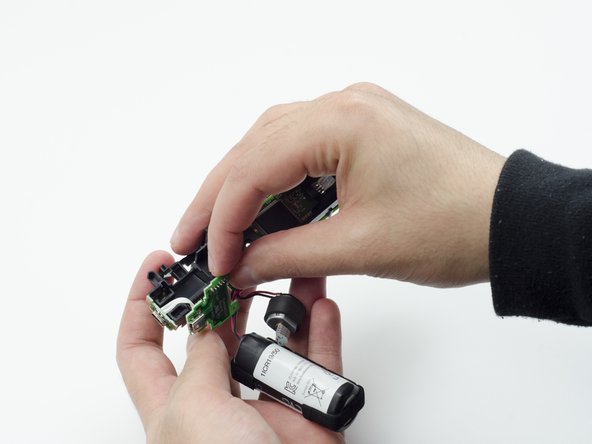
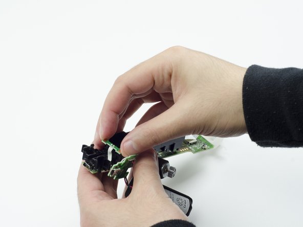
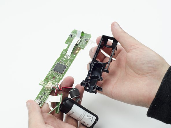
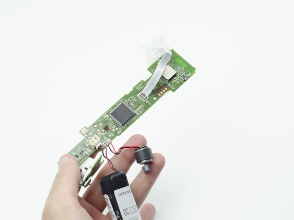
    • Using a soldering iron, carefully desolder the wires from the board. For help with desoldering, please check out this guide: How To Solder and Desolder Connections

    • In order to install the new rumble motor, you must solder the wires of the new motor to the circuit board.

ゴール

作成者

4人の作成者と共同で作成されました。

Sarah Shand

メンバー登録日: 02/20/17

1,885 ポイント

7のガイドは作成済み

チーム

USF Tampa, Team S3-G1, Sullivan Spring 2017 USF Tampa, Team S3-G1, Sullivan Spring 2017人のメンバー

USFT-SULLIVAN-S17S3G1

3 メンバー

13のガイドは作成済み

コメント 1 件

Step 7, there are 2 screws at the top near the white spherical piece holding the PCB on place that also need to be removed before you can lift it out

Steve Massart - 返信

コメントを追加

統計データ:

過去 24時間: 0

過去 7 日: 17

過去 30 日: 23

今までの合計 1,466