メインコンテンツにスキップ

Netgear WGR614v9 Capacitor Replacement

必要な工具と部品

  1. Netgear WGR614v9 Capacitor Replacement, Lower Case: 手順 1、 1の画像 1
    • Rotate the device so that the bottom is facing up.

  2. Netgear WGR614v9 Capacitor Replacement: 手順 2、 2の画像 1 Netgear WGR614v9 Capacitor Replacement: 手順 2、 2の画像 2
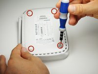
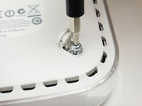
    • Lift up all four rubber pads on the bottom of the router with the plastic opening tool.

    • Be careful not to pull the rubber pads all the way out when lifting as they are difficult to reinsert.

  3. Netgear WGR614v9 Capacitor Replacement: 手順 3、 2の画像 1 Netgear WGR614v9 Capacitor Replacement: 手順 3、 2の画像 2
    • Unscrew the four 11.8 mm T-8 torx screws from the bottom of the router.

  4. Netgear WGR614v9 Capacitor Replacement: 手順 4、 1の画像 1
    • Lift the bottom casing straight up from the router.

  5. Netgear WGR614v9 Capacitor Replacement, Motherboard: 手順 5、 1の画像 1
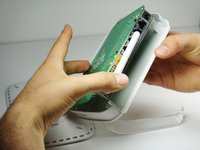
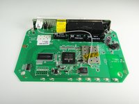
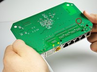
    • Remove the clear plastic casing by lifting it straight up from the router.

  6. Netgear WGR614v9 Capacitor Replacement: 手順 6、 2の画像 1 Netgear WGR614v9 Capacitor Replacement: 手順 6、 2の画像 2
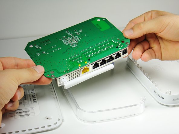
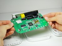
    • Separate the motherboard from the top shell by lifting it straight up from the router.

  7. Netgear WGR614v9 Capacitor Replacement, Capacitor: 手順 7、 2の画像 1 Netgear WGR614v9 Capacitor Replacement, Capacitor: 手順 7、 2の画像 2
    • Rotate the motherboard so that the top is facing up.

    • Set the motherboard on a flat clean surface.

  8. Netgear WGR614v9 Capacitor Replacement: 手順 8、 2の画像 1 Netgear WGR614v9 Capacitor Replacement: 手順 8、 2の画像 2
    • The capacitor can be found at the location shown.

  9. Netgear WGR614v9 Capacitor Replacement: 手順 9、 2の画像 1 Netgear WGR614v9 Capacitor Replacement: 手順 9、 2の画像 2
    • Rotate the motherboard so that the bottom is facing up.

    • Locate the two soldered contacts of the capacitor.

  10. Netgear WGR614v9 Capacitor Replacement: 手順 10、 3の画像 1 Netgear WGR614v9 Capacitor Replacement: 手順 10、 3の画像 2 Netgear WGR614v9 Capacitor Replacement: 手順 10、 3の画像 3
    • Rotate the motherboard 180 degrees.

    • Do not refer to the pictures in this step for proper de-soldering and soldering techniques. They are for illustration purposes only.

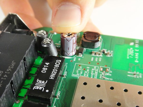
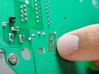
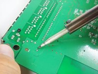
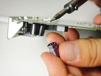
    • Refer to this link for proper de-soldering and soldering techniques.

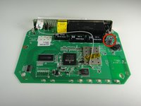
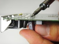
    • Pull the capacitor from the other side of the circuit board once the solder is liquified.

    • To replace the capacitor, orient the negative side of the capacitor (indicated by a white stripe and a negative sign) so that it aligns with the shaded white region of the circle indicating the capacitor's position on the motherboard.

終わりに

To reassemble your device, follow these instructions in reverse order.

ある他の人がこのガイドを完成しました。

作成者

7人の作成者と共同で作成されました。

Kyle Moore

メンバー登録日: 10/03/11

95 ポイント

1ガイドが承認済み

チーム

Cal Poly, Team 21-24, Maness Fall 2011 Cal Poly, Team 21-24, Maness Fall 2011人のメンバー

CPSU-MANESS-F11S21G24

4 メンバー

11のガイドは作成済み

コメント 1 件

looks like that's a 220microF at 25V right ?

probably better to replace it with a similar 220microF, but with higher voltage rating.

email_etran - 返信

コメントを追加

統計データ:

過去 24時間: 0

過去 7 日: 2

過去 30 日: 5

今までの合計 3,201