メインコンテンツにスキップ

このバージョンは誤った内容を含んでいる可能性があります。最新の承認済みスナップショットに切り替えてください。

必要な工具と部品

  1. この手順は未翻訳です。 翻訳を手伝う。

    : 手順 1、 1の画像 1
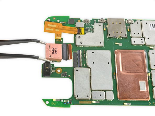
    • Prepare an iOpener and lay it over the rear case to soften the adhesive on securing the rear case to the phone.

  2. この手順は未翻訳です。 翻訳を手伝う。

    : 手順 2、 2の画像 1 : 手順 2、 2の画像 2
    • Use a plastic opening tool to pry the rear case off of the rest of the device.

    • Remove the rear case.

    • The wireless charging coil may try to stick to the rear case, so make sure to remove it from the case before fully separating the rear case from the rest of the device.

  3. この手順は未翻訳です。 翻訳を手伝う。

    : 手順 3、 1の画像 1
    • Remove the midframe bezel.

  4. この手順は未翻訳です。 翻訳を手伝う。

    : 手順 4、 1の画像 1
    • Remove the four Torx T5 screws securing the midframe plate.

  5. この手順は未翻訳です。 翻訳を手伝う。

    : 手順 5、 1の画像 1
    • Remove the midframe.

  6. この手順は未翻訳です。 翻訳を手伝う。

    : 手順 6、 2の画像 1 : 手順 6、 2の画像 2
    • Use the point of a spudger to pop up the battery connector.

  7. この手順は未翻訳です。 翻訳を手伝う。

    : 手順 7、 2の画像 1 : 手順 7、 2の画像 2
    • Fold the wireless charging coil away from the battery.

  8. この手順は未翻訳です。 翻訳を手伝う。

    : 手順 8、 2の画像 1 : 手順 8、 2の画像 2
    • Use a spudger to gently pry the battery up from the rest of the device.

    • The battery is secured with some moderate adhesive, so some force may be necessary.

  9. この手順は未翻訳です。 翻訳を手伝う。

    : 手順 9、 1の画像 1
    • Remove the four Torx T5 screws securing the lower antenna board to the motherboard.

  10. この手順は未翻訳です。 翻訳を手伝う。

    : 手順 10、 2の画像 1 : 手順 10、 2の画像 2
    • Remove the lower antenna board.

  11. この手順は未翻訳です。 翻訳を手伝う。

    : 手順 11、 2の画像 1 : 手順 11、 2の画像 2
    • Remove the SIM card holder/volume button rocker.

  12. この手順は未翻訳です。 翻訳を手伝う。

    : 手順 12、 2の画像 1 : 手順 12、 2の画像 2
    • Carefully lift up the motherboard to expose the display connector.

  13. この手順は未翻訳です。 翻訳を手伝う。

    : 手順 13、 2の画像 1 : 手順 13、 2の画像 2
    • Use the flat end of a spudger to flip up the retaining flap on the display ZIF connector.

    • Pull the display ribbon cable free of the connector.

    • Disconnecting the display ribbon cable makes it easier to remove the rear-facing camera, but it is not strictly necessary.

  14. この手順は未翻訳です。 翻訳を手伝う。

    : 手順 14、 2の画像 1 : 手順 14、 2の画像 2
    • Use the flat end of a spudger to flip up the black retaining flap on the front-facing camera ZIF connector.

    • Removing the front-facing camera makes it easier to remove the rear-facing camera, but it is not strictly necessary.

  15. この手順は未翻訳です。 翻訳を手伝う。

    : 手順 15、 2の画像 1 : 手順 15、 2の画像 2
    • Remove the front-facing camera.

  16. この手順は未翻訳です。 翻訳を手伝う。

    : 手順 16、 2の画像 1 : 手順 16、 2の画像 2
    • Use the flat end of a spudger to flip up the tan retaining flap on the rear-facing camera ZIF connector.

  17. この手順は未翻訳です。 翻訳を手伝う。

    : 手順 17、 3の画像 1 : 手順 17、 3の画像 2 : 手順 17、 3の画像 3
    • Remove the rear-facing camera.

ゴール

3 の人々がこのガイドを完成させました。

Geoff Wacker

メンバー登録日: 09/30/13

90,091 ポイント

89のガイドは作成済み

2 件のコメント

Nice tut. However, I couldn't remove the 2 screws on the side of the USB connector. They seem to be rotating loosely with a trembling sound. Any ideas how to remove it?.

vdamiani - 返信

They’re not turning in the second section. The screw is just stuck in the black piece. Try using very pointed tweezers to help remove the screws. Put the points just underneath the screw head and hold it up as you unscrew it.

Rongwey - 返信

コメントを追加

統計データ:

過去 24時間: 0

過去 7 日: 0

過去 30 日: 13

今までの合計 2,050