メインコンテンツにスキップ

このバージョンは誤った内容を含んでいる可能性があります。最新の承認済みスナップショットに切り替えてください。

必要な工具と部品

  1. , 底ケース: 手順 1、 1の画像 1
    • 底ケースを固定している以下の10本のネジを外します。

    • 13.5(14.1)mm プラスネジー3本

    • 3 mm プラスネジー7本

    • このネジを外すときには、ネジが少し斜めに装着されていることに注意してください。再インストールの際は、同じように取り付けてください。

  2. : 手順 2、 1の画像 1
    • 両手を使用して排気口の近くから底ケースを持ち上げて、上部ケースに固定している2本のクリップを外します。

    • 底ケースを取り外して脇に置きます。

  3. , バッテリーコネクタ: 手順 3、 2の画像 1 , バッテリーコネクタ: 手順 3、 2の画像 2
    • ※特定の修理(ハードディスクドライブなど)の場合はバッテリーを取り外す必要はありませんが、マザーボード上で誤ってショートさせてしまうのを防ぐ事が出来るので推奨されます。バッテリーを外さない場合は、マザーボード上の部品が帯電している可能性があるので注意してください。

    • ナイロンスパッジャーの端を使って、バッテリーコネクターをメイン基板上のソケットから持ち上げてください。

    • ソケットから接続を外す際、コネクターの縦側の両サイドを上向きに持ち上げると簡単です。

  4. : 手順 4、 1の画像 1
    • バッテリケーブルをソケットから離すように少し曲げておき、作業中に誤ってメイン基板に接触しないようにします。

  5. , 左側ファン: 手順 5、 1の画像 1
    • 基板に左側ファンを固定している3.4 mm T6トルクスネジを3本外します。

    • あるモデルでは、T6トルクスネジが3.1 mmの長さのものがあります。

  6. : 手順 6、 3の画像 1 : 手順 6、 3の画像 2 : 手順 6、 3の画像 3
    • スパッジャーの平面側先端を使って、基板から左側ファンのコネクターの接続を外します。

    • コネクタを解放するにはファンケーブルのワイヤ下からスパッジャーの平面側先端を水平に差し込み、ツイストすると作業が進みます。

    • ファン用のソケットとコネクタは2番目と3番目の画像で確認できます。スパッジャーでファンコネクターを持ち上げてソケットから外す際、プラスチックのファン用ソケットにダメージを与えないようご注意ください。2番目の画像から基板のレイアウトが確認できます。お持ちの基板とは若干異なる箇所があるかもしれませんが、ファン用ソケットは同じはずです。

  7. : 手順 7、 1の画像 1
    • 上部ケースから左側ファンを持ち上げて取り出します。

  8. , ロジックボード: 手順 8、 1の画像 1
    • スパッジャーの平面側先端を使って、ロジックボード上のソケットから右側のファンコネクターを持ち上げます。

    • コネクタを外すには、ファンケーブルのワイヤの下からスパッジャーをひねりながら引き上げると上手くいきます。

  9. : 手順 9、 2の画像 1 : 手順 9、 2の画像 2
    • ロジックボードに右側ファンを固定している3.4 mm (3.1 mm) T6トルクスネジを3本外します。

    • ロジックボード上の外れた部分から右側ファンを持ち上げます。

  10. : 手順 10、 1の画像 1
    • ロジックボード上のソケットからカメラケーブルを引き離します。

    • カメラケーブルの接続を外す際は、上に向かって引き抜かないでください。ケーブルを上向きに引くとケーブルとロジックボード両方にダメージを与えてしまうことがあります。ロジックボードの表面に対して平行にケーブルを引いてください。

  11. : 手順 11、 1の画像 1
    • スパッジャーの平面側先端を使って、ロジックボード上のソケットからAirPort/Bluetoothコネクタを引き上げます。

  12. : 手順 12、 1の画像 1
    • スパッジャーの平面側先端を使って、ロジックボード上のソケットから光学ドライブコネクタを引き上げます。

  13. : 手順 13、 1の画像 1
    • コネクタの下から接続を引き上げて、ハードドライブ/赤外線センサケーブルの接続をロジックボード上のソケットから外します。

  14. : 手順 14、 1の画像 1
    • スパッジャーの平面側先端を使って、サブウーハー/右側スピーカーのコネクタをロジックボード上のソケットから引き上げて、接続を外します。

    • ワイヤの下から持ち上げてください。

  15. : 手順 15、 2の画像 1 : 手順 15、 2の画像 2
    • ロジックボードにキーボード/トラックパッドケーブルのカバーを固定している1.5 mm ( 1.2 mm )プラスネジを2本外します。

    • ロジックボードからカバーを取り出します。

  16. : 手順 16、 1の画像 1
    • スパッジャーの平面側先端を使って、ロジックボード上のソケットからトラックパッドのコネクタを引き上げます。

  17. : 手順 17、 2の画像 1 : 手順 17、 2の画像 2
    • 指の先でキーボードリボンケーブルのZIFソケット上の固定フラップを裏返します。

    • 蝶番の固定フラップのみ裏返してください。ソケット自体には接触しないでください。

    • スパッジャーの先端を使って、キーボードリボンケーブルをソケットから引き抜きます。

  18. : 手順 18、 1の画像 1
    • スパッジャーの平面側先端を使って、基板上のソケットからバッテリーインディケーターのコネクタを持ち上げます。

  19. : 手順 19、 2の画像 1 : 手順 19、 2の画像 2
    • ディスプレイデータケーブルに固定されたプラスチックのプルタブを掴み、デバイスのDC-In側に向けて回します。

    • ディスプレイデータケーブルをロジックボード上のソケットから引き抜きます。

    • ディスプレイデータケーブルを上に引き上げないでください。ケーブルをロジックボードの表面に対して水平に引っ張ります。

  20. : 手順 20、 2の画像 1 : 手順 20、 2の画像 2
    • スパッジャーのの先端を使って、キーボードバックライトのリボンケーブルZIFソケット上の固定フラップを引き抜きます。

    • 蝶番の固定フラップを引き抜いているか確認してください。ソケットには触れないでください。

    • キーボードのバックライトリボンケーブルをソケットから引き抜きます。

  21. : 手順 21、 1の画像 1
    • 次の9本のネジを外します。

    • ロジックボード上の3.4 mm ( 3.1 mm) T6トルクスネジー7本

    • DC-In ボード上の8 mm T6トルクスネジー2本

  22. : 手順 22、 3の画像 1 : 手順 22、 3の画像 2 : 手順 22、 3の画像 3
    • 作業中光学ドライブケーブルとI/O端子に掛からないよう注意しながら、上部ケースからロジックボードアセンブリを左側からゆっくりと取り出します。

    • 必要に応じて、スパッジャーの平面側先端を使って上部ケースからマイクを取り出します。

    • 上部ケースの横からロジックボードのI/O端子側を引き抜き、ロジックボードアセンブリを取り出します。

  23. この手順は未翻訳です。 翻訳を手伝う。

    : 手順 23、 1の画像 1
    • Remove the two 7.5 mm ( 7.2 mm )Tri-point screws securing the battery to the upper case.

  24. この手順は未翻訳です。 翻訳を手伝う。

    : 手順 24、 1の画像 1
    • Carefully peel the battery warning label off the upper case between the battery and the optical drive to reveal an additional Tri-point screw.

    • Remove the last 7.5 mm ( 7.2 mm ) Tri-point screw securing the battery to the upper case.

    • Do not remove the label from the battery.

  25. この手順は未翻訳です。 翻訳を手伝う。

    : 手順 25、 1の画像 1
    • Use the attached plastic pull tab to remove the battery from the upper case.

  26. この手順は未翻訳です。 翻訳を手伝う。

    : 手順 26、 2の画像 1 : 手順 26、 2の画像 2
    • Remove the two Phillips screws securing the hard drive bracket to the upper case.

    • These screws are captive in the hard drive bracket.

    • Remove the hard drive bracket from the upper case.

  27. この手順は未翻訳です。 翻訳を手伝う。

    : 手順 27、 1の画像 1
    • Using its attached pull tab, lift the hard drive out of the upper case.

    • Don't try to completely remove it yet, as it is still connected to the hard drive cable.

  28. この手順は未翻訳です。 翻訳を手伝う。

    : 手順 28、 2の画像 1 : 手順 28、 2の画像 2
    • Pull the hard drive connector out of its socket on the hard drive.

    • Pull on the connector, not the cable itself.

    • Remove the hard drive and set it aside.

  29. この手順は未翻訳です。 翻訳を手伝う。

    : 手順 29、 1の画像 1
    • Remove the following four screws securing the hard drive/IR sensor cable to the upper case:

    • Two 2.5 mm ( 2.9 mm ) Phillips screws

    • Two 10 mm ( 9.6 mm ) Phillips screws

  30. この手順は未翻訳です。 翻訳を手伝う。

    : 手順 30、 2の画像 1 : 手順 30、 2の画像 2
    • Carefully peel the IR sensor cable off the adhesive securing it to the upper case.

    • Pull the hard drive bracket/IR sensor housing away from the side of the upper case.

    • Remove the hard drive/IR sensor cable from the upper case.

  31. この手順は未翻訳です。 翻訳を手伝う。

    : 手順 31、 2の画像 1 : 手順 31、 2の画像 2
    • Use the tip of a spudger to pry the four antenna connectors up from their sockets on the AirPort/Bluetooth board.

  32. この手順は未翻訳です。 翻訳を手伝う。

    : 手順 32、 2の画像 1 : 手順 32、 2の画像 2
    • De-route all four antenna cables from their channels in the AirPort/Bluetooth housing.

    • De-route the camera cable from its channel in the AirPort/Bluetooth housing.

  33. この手順は未翻訳です。 翻訳を手伝う。

    : 手順 33、 2の画像 1 : 手順 33、 2の画像 2
    • Remove the following two screws:

    • One 8.6 mm ( 8.4 mm ) Phillips screw

    • One 3.9 mm Phillips screw

    • Remove the AirPort/Bluetooth assembly from the upper case, minding any cables that may get caught.

  34. この手順は未翻訳です。 翻訳を手伝う。

    : 手順 34、 2の画像 1 : 手順 34、 2の画像 2
    • Remove the three 3.5 mm ( 3.3 mm ) T6 Torx screws securing the optical drive to the upper case.

    • Lift the optical drive near its connector and pull it away from the upper case to remove it from the computer.

  35. この手順は未翻訳です。 翻訳を手伝う。

    : 手順 35、 2の画像 1 : 手順 35、 2の画像 2
    • Remove the following six screws securing the subwoofer and right speaker to the upper case:

    • Two 3.2 mm ( 3.0 mm ) Phillips screws.

    • Two 12.3 mm Phillips screws.

    • One 2.5 mm Phillips screw.

    • One 8.3 mm ( 8.1 mm ) Phillips screw.

    • Lift the subwoofer and right speaker assembly out of the upper case.

  36. この手順は未翻訳です。 翻訳を手伝う。

    : 手順 36、 2の画像 1 : 手順 36、 2の画像 2
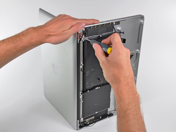
    • Remove the 8.6 mm Phillips screw securing the antenna/camera cable retainer to the top left portion of the upper case.

    • Remove the antenna/camera cable retainer from the upper case.

    • Check your new part: The antenna cable and plate attached to the upper case may need to be transferred. Take care peeling the metal plate off, an adhesive is used to hold it in place.

  37. この手順は未翻訳です。 翻訳を手伝う。

    : 手順 37、 2の画像 1 : 手順 37、 2の画像 2
    • Remove the 8.6 mm ( 7.0 mm ) Phillips screw securing the display data cable retainer to the top right portion of the upper case.

    • Remove the display data cable retainer from the upper case.

  38. この手順は未翻訳です。 翻訳を手伝う。

    : 手順 38、 1の画像 1
    • Remove two of the three 6 mm T6 Torx screws securing the right side of the display to the upper case.

    • We purposely have you leave one screw attaching the display to the upper case to aid in future steps.

  39. この手順は未翻訳です。 翻訳を手伝う。

    : 手順 39、 1の画像 1
    • Remove two of the three 6 mm T6 Torx screws securing the left side of the display to the upper case.

    • We purposely have you leave one screw attaching the display to the upper case to aid in future steps.

  40. この手順は未翻訳です。 翻訳を手伝う。

    : 手順 40、 1の画像 1
    • Open your MacBook Pro so the display is perpendicular to the upper case.

    • Place your opened MacBook Pro on a table as pictured.

    • While holding the display and upper case together with your left hand, remove the remaining T6 Torx screw from the upper display bracket.

  41. この手順は未翻訳です。 翻訳を手伝う。

    : 手順 41、 1の画像 1
    • Be sure to hold the display and upper case together with your left hand. Failure to do so may cause the freed display/upper case to fall, potentially damaging each component.

    • Remove the last remaining T6 Torx screw securing the display to the upper case.

  42. この手順は未翻訳です。 翻訳を手伝う。

    : 手順 42、 3の画像 1 : 手順 42、 3の画像 2 : 手順 42、 3の画像 3
    • Grab the upper case with your right hand and rotate it slightly toward the top of the display so the upper display bracket clears the edge of the upper case.

    • Rotate the display slightly away from the upper case.

    • Lift the display up and away from the upper case, minding any brackets or cables that may get caught.

  43. この手順は未翻訳です。 翻訳を手伝う。

    : 手順 43、 1の画像 1
    • Before proceeding, check if your replacement upper case comes with the battery level indicator installed. If not, you'll need to transfer the battery level indicator to your new upper case.

    • If your replacement includes the battery level indicator, stop here.

    • Remove three 2.0 mm Phillips #00 screws securing the battery level indicator to the upper case.

  44. この手順は未翻訳です。 翻訳を手伝う。

    : 手順 44、 2の画像 1 : 手順 44、 2の画像 2
    • Use the tip of a spudger to gently pry up the edge of the metal shield covering the battery level indicator cable.

    • The metal shield is lightly adhered to the upper case and shouldn't require a lot of force.

    • This metal shield may need to be transferred to your new part.

    • Be careful not to damage the battery level indicator cable while prying.

  45. この手順は未翻訳です。 翻訳を手伝う。

    : 手順 45、 2の画像 1 : 手順 45、 2の画像 2
    • Remove the battery level indicator.

    • The battery level indicator cable is lightly adhered to the upper case—use a combination of the flat end of your spudger and gentle peeling to remove it.

    • Be careful not to snag the battery level indicator cable on the metal shield.

  46. この手順は未翻訳です。 翻訳を手伝う。

    : 手順 46、 1の画像 1
    • Remove the battery level indicator button.

    • Note the orientation for installing in your replacement upper case—the larger, shiny side faces out.

    • Depending on your replacement upper case, you may also need to transfer your trackpad now. Follow this guide to remove and transfer your trackpad.

ゴール

34 の人々がこのガイドを完成させました。

作成者

6人の作成者と共同で作成されました。

Miroslav Djuric

158,313 ポイント

144のガイドは作成済み

0 件のコメント

コメントを追加

統計データ:

過去 24時間: 3

過去 7 日: 18

過去 30 日: 41

今までの合計 40,172