メインコンテンツにスキップ

このバージョンは誤った内容を含んでいる可能性があります。最新の承認済みスナップショットに切り替えてください。

必要な工具と部品

  1. , バッテリー: 手順 1、 1の画像 1
    • コインやスパッジャーを使って、バッテリーロックネジを90度時計回りに回転させます。

  2. : 手順 2、 1の画像 1
    • コンピュータからバッテリーを持ち上げます。

  3. この手順は未翻訳です。 翻訳を手伝う。

    : 手順 3、 1の画像 1
    • Remove the three evenly-spaced Phillips screws from along the rear wall of the battery compartment.

    • The screws are captive to the metal memory cover.

    • When replacing the battery casing, use a spudger to re-insert the foam cushioning behind the rear wall for propper battery spacing.

  4. : 手順 4、 1の画像 1
    • L字型メモリカバーを持ち上げ、右側にスライドして、コンピュータから持ち上げます。

  5. この手順は未翻訳です。 翻訳を手伝う。

    : 手順 5、 1の画像 1
    • Remove the following 3 screws:

    • One 11 mm Phillips #00 in the middle of the case.

    • Two 14.5 mm Phillips #00.

    • If the screws stick in the case, you can use a magnetized screwdriver to draw them out.

    • The shorter of the three screws goes in the middle.

  6. この手順は未翻訳です。 翻訳を手伝う。

    : 手順 6、 1の画像 1
    • Remove the following 3 screws from the rear wall of the battery compartment:

    • Two 3 mm Phillips #00. (A1181 has three 3 mm screws and one 4 mm.)

    • One 4 mm Phillips #00 on the right side.

    • When reinstalling these screws, press gently on the lower case to line up the screw holes.

    • These screws easily strip, so be careful while taking these particular screws out.

  7. この手順は未翻訳です。 翻訳を手伝う。

    : 手順 7、 1の画像 1
    • Remove the two 6 mm Phillips #00 screws from either side of the right wall of the battery compartment (not the ones closest to the battery connector).

  8. この手順は未翻訳です。 翻訳を手伝う。

    : 手順 8、 1の画像 1
    • Remove the four 3 mm indicated Phillips #00 screws from the front wall of the battery compartment. When working from the left, remove the 2nd, 4th, 7th and 9th screw.

  9. この手順は未翻訳です。 翻訳を手伝う。

    : 手順 9、 1の画像 1
    • Remove the following 4 screws from the back of the computer:

    • Two 7 mm shouldered Phillips on the far sides.

    • Two 10.5 mm Phillips toward the center.

    • Do not over-tighten these; you can cause the case to distort.

  10. この手順は未翻訳です。 翻訳を手伝う。

    : 手順 10、 1の画像 1
    • Remove the two 5.2 mm shouldered Phillips #00 screws from the optical side of the computer.

    • It is not necessary to remove the similar screws on the other side of the computer.

  11. この手順は未翻訳です。 翻訳を手伝う。

    : 手順 11、 1の画像 1
    • Starting near the display and working around to the front of the computer, pry up on the upper case. It is held with clips on the right above the optical drive. These will release with some firm lifting pressure.

    • Be careful when prying up the upper case. It's very easy to slice open a fingertip and thus provide the blood sacrifice the Mac gods sometimes require of those who insist on doing their own repairs.

    • There's a trackpad and keyboard ribbon connecting the upper case to the logic board, so don't pull the upper case off entirely just yet.

    • If you have trouble getting the clips to release, be careful that you are not prying the plastic top of the upper case away from its metal frame.

  12. この手順は未翻訳です。 翻訳を手伝う。

    : 手順 12、 1の画像 1
    • While holding up the upper case (from the bottom or the top), use a spudger to pry up the orange trackpad and keyboard cable from its connector.

    • Take care to pry between the black socket and the white connector. You might have to pry on both sides for it to release properly.

    • Do not pry from the bottom or the top, but from the sides.

    • If you happen to break your upper case cable when removing the upper case, we stock the cable individually and we have a guide that makes replacing it easy.

  13. この手順は未翻訳です。 翻訳を手伝う。

    : 手順 13、 1の画像 1
    • If you have a silver upper case cable, skip to Step 22.

    • If you have a brown upper case cable, follow this and the following steps to replace your upper case cable.

    • Carefully peel the upper case cable off the adhesive securing it to the upper case.

  14. この手順は未翻訳です。 翻訳を手伝う。

    : 手順 14、 2の画像 1 : 手順 14、 2の画像 2
    • Use the flat end of a spudger to carefully peel up the adhesive around the perimeter of the plastic panel stuck to the underside of the trackpad.

    • Remove the panel from the upper case.

  15. この手順は未翻訳です。 翻訳を手伝う。

    : 手順 15、 2の画像 1 : 手順 15、 2の画像 2
    • Use the tip of a spudger or your fingernail to flip up the retaining flap on the upper case cable ZIF socket near the keyboard cable.

    • Be sure you are prying up on the retaining flap, not the socket itself.

  16. この手順は未翻訳です。 翻訳を手伝う。

    : 手順 16、 1の画像 1
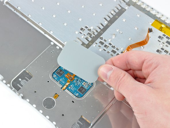
    • Gently peel up the section of the upper case cable stuck to the keyboard ribbon cable, being careful not to disturb the keyboard ribbon cable in the process.

  17. この手順は未翻訳です。 翻訳を手伝う。

    : 手順 17、 1の画像 1
    • Pull the top upper case ribbon cable connector out of its socket under the trackpad.

  18. この手順は未翻訳です。 翻訳を手伝う。

    : 手順 18、 2の画像 1 : 手順 18、 2の画像 2
    • Use the tip of a spudger to flip up the retaining flap on the mouse button ribbon cable socket.

    • Be sure you are prying up on the retaining flap, not the socket itself.

  19. この手順は未翻訳です。 翻訳を手伝う。

    : 手順 19、 1の画像 1
    • Pull the mouse button ribbon cable out of its socket.

  20. この手順は未翻訳です。 翻訳を手伝う。

    : 手順 20、 1の画像 1
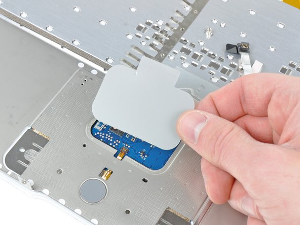
    • Use the flat end of a spudger to help peel the last portion of the upper case ribbon cable off the adhesive securing it to the underside of the trackpad.

  21. この手順は未翻訳です。 翻訳を手伝う。

    : 手順 21、 1の画像 1
    • Remove the upper case cable from the upper case.

  22. この手順は未翻訳です。 翻訳を手伝う。

    : 手順 22、 2の画像 1 : 手順 22、 2の画像 2
    • Use the flat end of a spudger to carefully peel up the adhesive around the perimeter of the plastic panel stuck to the underside of the trackpad.

    • Remove the panel from the upper case.

  23. この手順は未翻訳です。 翻訳を手伝う。

    : 手順 23、 1の画像 1
    • Carefully peel the upper case cable and the piece of clear tape off the bottom of the upper case.

  24. この手順は未翻訳です。 翻訳を手伝う。

    : 手順 24、 2の画像 1 : 手順 24、 2の画像 2
    • Use the tip of a spudger to flip up the retaining flap on the upper case cable ZIF socket.

    • Be sure you are prying up on the hinged retaining flap, not the socket itself.

  25. この手順は未翻訳です。 翻訳を手伝う。

    : 手順 25、 1の画像 1
    • Pull the upper case cable out of its socket and remove it from the upper case.

ゴール

33 の人々がこのガイドを完成させました。

作成者

3人の作成者と共同で作成されました。

Andrew Bookholt

586,296 ポイント

619のガイドは作成済み

コメント 1 件

Andrew you are the best.Very easy to follow instructions.I will replace mind,90 points

Mosua Patrick - 返信

コメントを追加

統計データ:

過去 24時間: 1

過去 7 日: 8

過去 30 日: 39

今までの合計 23,590