メインコンテンツにスキップ

この翻訳は、ソースガイドの最新の更新を反映していない可能性があります。 翻訳の更新に協力してください。 または ソースガイドを参照してください

必要な工具と部品

  1. , 下部ケース: 手順 1、 1の画像 1
    この手順で使用する道具:
    P5 Pentalobe Screwdriver Retina MacBook Pro and Air
    $11.99
    購入する
    • まず、コンピューターをシャットダウンし、柔らかい素材の表面上に天面を下にして置きます。

    • 以下の10本のネジを外します:

    • 星型ペンタローブネジ 8mm 2本

    • 星型ペンタローブネジ 2.5mm 8本

    • 星型ペンタローブネジを外す際に必要な特別ドライバーはこちらで購入できます。

  2. : 手順 2、 1の画像 1
    • ディスプレイと下部ケースの間に指を入れ、下部ケースを引き上げて外します。

  3. , バッテリー: 手順 3、 2の画像 1 , バッテリー: 手順 3、 2の画像 2
    • この手順では、作業中にパーツがショートしないように、バッテリーを取り外します。

    • スパッジャーの平面側先端を使用して、バッテリーコネクター両側の短辺を持ち上げて、ロジックボードのソケットから外します。

    • アクシデントでコネクタがソケットに接触しないように、バッテリケーブルをロジックボードから少し離して反対側に折り曲げます。

  4. , SSD: 手順 4、 1の画像 1
    • SSDをロジックボードに固定している1つの2.9 mm T5トルクスネジを取り外します。

  5. : 手順 5、 2の画像 1 : 手順 5、 2の画像 2
    • 一方の手でSSDを掴み引き上げて、スパッジャーを使って差し込み、SSDの解放側を持ち上げます。

    • SSDを過剰に高くまで持ち上げないで下さい。

    • ドライブをソケットからまっすぐ引いてロジックボードから取り外します。

    • SSDを再装着する際は固定ネジを取り付ける前に、SSDが正しい位置に取り付けられているか確認してください。

  6. , I/O ボードケーブル: 手順 6、 1の画像 1
    • スパッジャーの平面側先端を使って、I/Oボード上のソケットからI/Oボードケーブルを持ち上げます。

  7. : 手順 7、 1の画像 1
    • ファンに留められた接着剤からI/Oボードケーブルを剥がします。

  8. : 手順 8、 2の画像 1 : 手順 8、 2の画像 2
    • スパッジャーの平面側先端を使用して、I/Oボードコネクタを持ち上げて、ロジックボードのソケットから取り外します。

    • コネクタをソケットから外すときは、コネクタをまっすぐ持ち上げてください。 ソケットはロジックボード上の非常に深いところにあり、コネクタの左右両側からこじ開けてしまうと、ロジックボードを損傷してしまうことがあります

    • I/Oボードケーブルを取り出します。

  9. , ファン: 手順 9、 1の画像 1
    • スパッジャーの先端を使って、ファンケーブルZIFソケットの保持フラップを持ち上げます。

    • ソケット自体ではなく、ヒンジのある保持フラップを持ち上げているか確認してください。

  10. : 手順 10、 1の画像 1
    • ファンを天蓋に固定している下記の3つのネジを取り外します。

    • 2つの5.2 mm T5 トルクスネジ

    • 1つの3.6 mm T5 トルクスネジ

  11. : 手順 11、 1の画像 1
    • 天蓋からファンを持ち上げて、ゆっくりとファンのリボンケーブルをソケットから引きながら、同時にファンを取り出します。

  12. , バッテリー: 手順 12、 1の画像 1
    • バッテリーを上部ケースに固定している次の5本のネジを外します:

    • 5.2mm T5トルクスネジ 2本

    • 6mm T5トルクスネジ 1本

    • 2.6mm T5トルクスネジ 2本

  13. : 手順 13、 1の画像 1
    • バッテリーを扱う際は、6つのリチウムポリマーセルに触れたり、絞らないでください。

    • バッテリーをロジックボードに最も近い端から持ち上げて、上部ケースから取り外します。

  14. , ロジックボード: 手順 14、 2の画像 1 , ロジックボード: 手順 14、 2の画像 2
    • スパッジャーの平面側先端を使って、I/Oボードの電源ケーブルを上部ケースに固定している接着ループを外します。

    • ロジックボードのソケットから電源ケーブルを引き抜いて、I/Oボードを取り外します。

    • ケーブルをロジックボード表面と平行にして、Air本体前方の端に向けて引っ張ります。

  15. : 手順 15、 2の画像 1 : 手順 15、 2の画像 2
    • スパッジャーの先端を使って、キーボードバックライトリボンケーブルのZIFソケット上の固定フラップを跳ね上げます。

    • ソケットではなく、蝶番で動く固定フラップのみを跳ね上げているか確認してください。

    • ソケットからキーボードリボンケーブルを引き抜きます。

  16. : 手順 16、 2の画像 1 : 手順 16、 2の画像 2
    • スパッジャーの先端や指の爪を使って、トラックパッドリボンケーブルのZIFソケット上の固定フラップを跳ね上げます。

    • ソケットではなく、蝶番で動く固定フラップのみを跳ね上げているか確認してください。

    • Airの前端に向けて、ソケットからトラックパッドリボンケーブルをまっすぐ引き抜きます。

  17. : 手順 17、 1の画像 1
    • スパッジャーの先端を使って、ロジックボードの切り込まれたスロットより右側スピーカーのケーブルを取り出します。

  18. : 手順 18、 1の画像 1
    • スパッジャーの平面側先端を使って、ロジックボード上のソケットから右側スピーカーケーブルコネクタを持ち上げて外します。

    • ケーブルの下から持ち上げてください。

  19. : 手順 19、 3の画像 1 : 手順 19、 3の画像 2 : 手順 19、 3の画像 3
    • ディスプレイデータケーブルのロックに付いている黒いプラスチックのフラップの下に、スパッジャーの先端を慎重に差し込んで、ロックをソケットから上向きに出します。

    • ディスプレイデータケーブル付近の上部ケースの角から小さなゴム製ガスケットを取り外します。

  20. : 手順 20、 1の画像 1
    • ソケットからロックを離しながら、ディスプレイデータケーブルをソケットから慎重に引き抜きます。

    • ディスプレイデータケーブルを外す際に上向きに引っ張ると、ソケットがロジックボードにダメージを与えてしまう可能性があります。ご注意ください。

  21. : 手順 21、 2の画像 1 : 手順 21、 2の画像 2
    • スパッジャーの平面側先端を使って、両方のアンテナケーブルコネクタをAirport /Bluetoothカードのソケットから持ち上げて取り外します。

  22. : 手順 22、 1の画像 1
    • ロジックボード上の切り欠きからアンテナケーブルを慎重に通して外します。

  23. : 手順 23、 1の画像 1
    • ロジックボードを上部ケースに固定している3.6mm T5トルクスネジを3本外します。

  24. : 手順 24、 1の画像 1
    • 壊れやすいヒートシンクと絡まりやすいケーブルに注意しながら、ロジックボードアセンブリを慎重に持ち上げて、上部ケースから取り外します。

  25. この手順は未翻訳です。 翻訳を手伝う。

    : 手順 25、 1の画像 1
    • Remove the small rubber gasket from the corner of the upper case nearest the I/O board.

  26. : 手順 26、 2の画像 1 : 手順 26、 2の画像 2
    • スパッジャーの先端を使って、マイクケーブルのZIFソケット上の固定フラップを注意深く跳ね上げます。

    • ソケットではなく、蝶番で動く固定フラップのみを跳ね上げているか確認してください。

    • ソケットからマイクリボンケーブルをまっすぐ引き抜きます。

  27. この手順は未翻訳です。 翻訳を手伝う。

    : 手順 27、 2の画像 1 : 手順 27、 2の画像 2
    • De-route the left speaker cable from the notch cut into the I/O board.

    • Use the flat end of a spudger to pry the left speaker cable connector up and out of its socket on the I/O board.

    • Pry up from beneath the wires.

  28. この手順は未翻訳です。 翻訳を手伝う。

    : 手順 28、 1の画像 1
    • Pull the camera cable parallel to the face of the I/O board toward the rear edge of the Air to disconnect it from its socket.

    • Do not lift upward on this cable as you disconnect it, as its socket may break off the logic board.

  29. : 手順 29、 1の画像 1
    • I/Oボードを上部ケースに固定している3.6mm T5トルクスネジを1本外します。

  30. この手順は未翻訳です。 翻訳を手伝う。

    : 手順 30、 1の画像 1
    • Carefully lift the I/O board from its edge nearest the logic board and remove it from the upper case.

  31. この手順は未翻訳です。 翻訳を手伝う。

    : 手順 31、 3の画像 1 : 手順 31、 3の画像 2 : 手順 31、 3の画像 3
    • Peel up the six cable loops securing the antenna cables to the upper case.

    • Gently pull the cable loops slightly out of the channel cut into the upper case one at a time.

    • Use your spudger to open up the plastic loops as you de-route the antenna cables through them.

    • Repeat this for all of the retaining loops.

  32. この手順は未翻訳です。 翻訳を手伝う。

    : 手順 32、 2の画像 1 : 手順 32、 2の画像 2
    • Remove the inner 4.9 mm T8 Torx screw securing each display hinge to the upper case (two screws total).

  33. この手順は未翻訳です。 翻訳を手伝う。

    : 手順 33、 1の画像 1
    • Open the display until it is perpendicular to the upper case and place it on a table as shown.

    • While holding the Air steady, remove the remaining 4.9 mm T8 Torx screw from the lower display bracket.

  34. この手順は未翻訳です。 翻訳を手伝う。

    : 手順 34、 1の画像 1
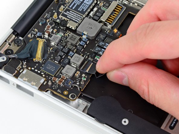
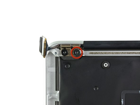
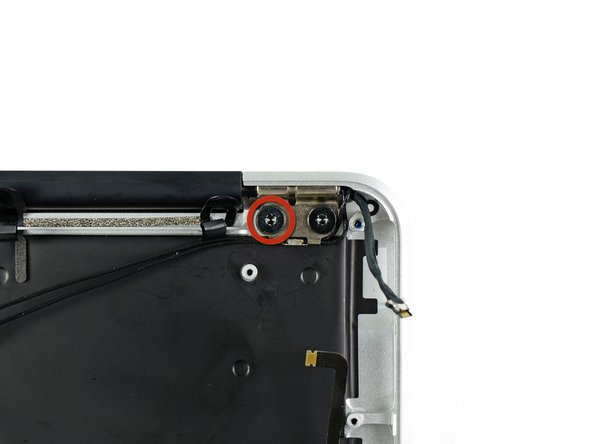
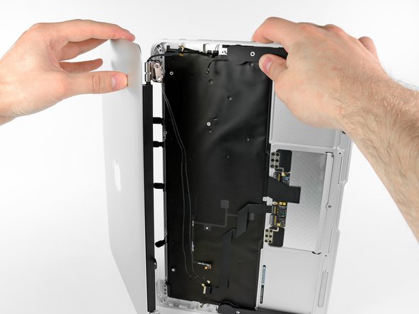
    • Before removing the last display screw, be sure to hold the display and upper case steady with your other hand. Failure to do so may allow the components to fall onto the table, causing potentially expensive damage.

    • Remove the last 4.9 mm T8 Torx screw securing the display to the upper case.

  35. この手順は未翻訳です。 翻訳を手伝う。

    : 手順 35、 2の画像 1 : 手順 35、 2の画像 2
    • Push the upper case slightly toward the display assembly, then rotate it away from the front of the display assembly.

    • Once the two display hinges have cleared the upper case, remove the display and set it aside.

  36. この手順は未翻訳です。 翻訳を手伝う。

    : 手順 36、 2の画像 1 : 手順 36、 2の画像 2
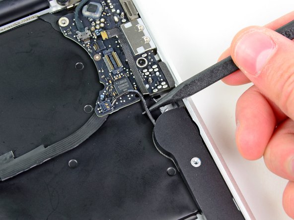
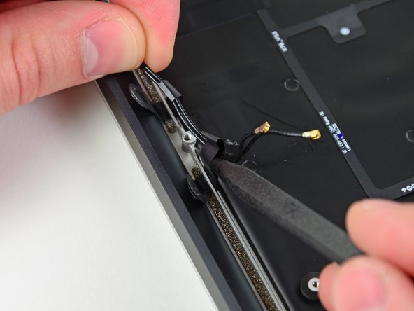
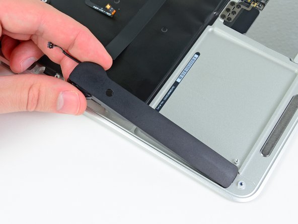
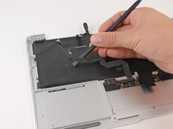
    • Use the flat end of a spudger to pry the right speaker off the adhesive securing it to the upper case.

    • Only pry up on the speaker from the areas of bare aluminum on the upper case. Prying up from the keyboard area may damage the keyboard and the speaker itself.

    • Remove the right speaker from the upper case.

  37. この手順は未翻訳です。 翻訳を手伝う。

    : 手順 37、 2の画像 1 : 手順 37、 2の画像 2
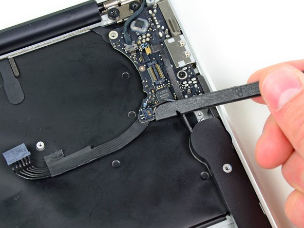
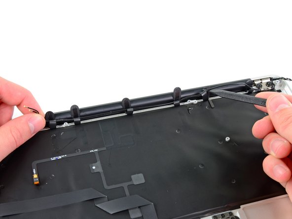
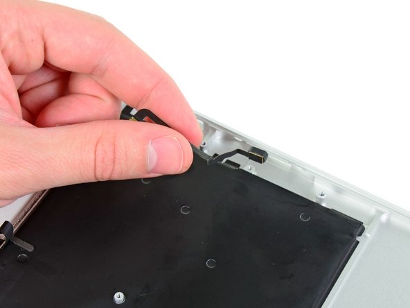
    • Use the flat end of a spudger to pry the left speaker off the adhesive securing it to the upper case.

    • Only pry up on the speaker from the areas of bare aluminum on the upper case. Prying up from the keyboard area may damage the keyboard and the speaker itself.

    • Remove the left speaker from the upper case.

  38. この手順は未翻訳です。 翻訳を手伝う。

    : 手順 38、 2の画像 1 : 手順 38、 2の画像 2
    • Use the tip of a spudger to pry the microphone away from the side of the upper case.

    • Remove the microphone from the upper case.

    • Upper case remains.

  39. この手順は未翻訳です。 翻訳を手伝う。

    : 手順 39、 3の画像 1 : 手順 39、 3の画像 2 : 手順 39、 3の画像 3
    • The ZIF connector for the keyboard ribbon cable is hidden under the cable itself.

    • Push/lift the keyboard ribbon cable off of the upper case with one hand.

    • With the other hand, use a spudger to flip up the retaining flap on the ZIF connector.

    • Once the retaining flap has been flipped up, carefully pull the ribbon cable straight out of its socket.

  40. この手順は未翻訳です。 翻訳を手伝う。

    : 手順 40、 2の画像 1 : 手順 40、 2の画像 2
    • Use the flat end of a spudger to separate the trackpad ribbon cable from the underside of the keyboard.

    • The cable is held in place with adhesive. Work carefully, and be sure to not let the spudger slip and damage any components.

  41. この手順は未翻訳です。 翻訳を手伝う。

    : 手順 41、 1の画像 1
    • Remove the six 1.5 mm Phillips #00 screws securing the trackpad to the upper case.

    • Check your replacement upper case—if it doesn't have this wide T5 screw, remove it to transfer into the replacement.

    • This is an adjustment screw to set the distance of the click of the trackpad—on reassembly, test the click and adjust this screw until it feels right.

  42. この手順は未翻訳です。 翻訳を手伝う。

    : 手順 42、 3の画像 1 : 手順 42、 3の画像 2 : 手順 42、 3の画像 3
    • Holding the upper case up off the table with one hand, gently push the trackpad up through the upper case.

    • Remove the trackpad from the upper case.

  43. : 手順 43、 1の画像 1
    • 上部ケースが残ります。

ゴール

44 の人々がこのガイドを完成させました。

以下の翻訳者の皆さんにお礼を申し上げます:

en jp

11%

railgunさんは世界中で修理する私たちを助けてくれています! あなたも貢献してみませんか?
翻訳を始める ›

作成者

7人の作成者と共同で作成されました。

Brett Hartt

メンバー登録日: 04/12/10

127,920 ポイント

143のガイドは作成済み

チーム

iFixit iFixit人のメンバー

Staff

135 メンバー

17,146のガイドは作成済み

8 件のコメント

I used this guide to replace the keyboard on my macbook air 11, mid 2011.

When I removed the perimeter screws on the keyboard, I then popped all of the 54 or so rivots. I bought a $34 keyboard and installed it with the perimeter screws. But then I bonded the top of each of the rivot shafts with a tiny amount of epoxy cement, after which I used a razor blade to shave each of them to be flush. After re-installing the backlight material, and reassembling the computer, it works PERFECTLY. The Apple store expert had told us that the computer could not be repaired. :-)

Bill Aldridge - 返信

I’ve bought a replacement keyboard with holes in every place where a rivot existed. So it doesn’t requires any work on the case for the remains of the rivots.

lardissone -

Thank you very much for your clear guide! Even though I had never opened a laptop before, I was able to dig down to my keyboard with your instructions and I'm typing this now with BOTH shift keys :-D

Note: unlike @Bill Aldridge I bought extra screws to replace the rivets and replaced all but four of the rivets using (at my Father's suggestion) flat sharp wire cutters to bite into the stumps of the rivets and then pop them out.

Adam Lee - 返信

Just replaced a top cover following this guide. It worked perfectly! Looks like this trusty old Air is going to get another couple of years of life. Didn't even want to try doing just the keyboard, that just seems brutal. Anyways, thanks for the guide!

nmirza - 返信

I’ve gone used this guide TWICE on the same laptop. My Girlfriend seems determined to keep breaking her laptop! ;-) I may have to buy some screws if there the a third time, some of them are getting a bit worn… Thanks for the guide (again).

nmirza - 返信

コメントを追加

統計データ:

過去 24時間: 2

過去 7 日: 23

過去 30 日: 55

今までの合計 54,448