メインコンテンツにスキップ

Logitech Webcam Pro 9000 Motherboard Replacement

必要な工具と部品

  1. Logitech Webcam Pro 9000 Motherboard Replacement, Front and Back Cover: 手順 1、 2の画像 1 Logitech Webcam Pro 9000 Motherboard Replacement, Front and Back Cover: 手順 1、 2の画像 2
    • Remove the two 8 mm Phillips #0 screws on the back cover.

    • The motherboard connects the two covers together. DO NOT separate the two yet.

    • There is a button that loosens as the Phillips screws are removed. Don't be alarmed if it falls out.

  2. Logitech Webcam Pro 9000 Motherboard Replacement: 手順 2、 2の画像 1 Logitech Webcam Pro 9000 Motherboard Replacement: 手順 2、 2の画像 2
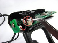
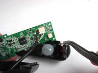
    • Remove the four 6mm Phillips #0 screws connecting the motherboard and front cover.

    • DO NOT detach the wire connecting the motherboard to the front cover.

  3. Logitech Webcam Pro 9000 Motherboard Replacement, Snapshot button: 手順 3、 3の画像 1 Logitech Webcam Pro 9000 Motherboard Replacement, Snapshot button: 手順 3、 3の画像 2 Logitech Webcam Pro 9000 Motherboard Replacement, Snapshot button: 手順 3、 3の画像 3
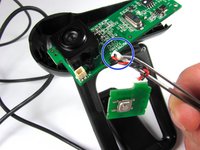
    • Grasp the white connector attaching the button chip wire to the motherboard.

    • Grab between the tabs and the socket.

    • Wiggle the connector back and forth to remove it from the connection box

    • Do not worry if you detach the red and black wire connection on the power button.

  4. Logitech Webcam Pro 9000 Motherboard Replacement, Microphone Connection: 手順 4、 2の画像 1 Logitech Webcam Pro 9000 Motherboard Replacement, Microphone Connection: 手順 4、 2の画像 2
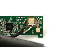
    • Grasp the white wire connector between the tabs and the socket.

    • Wiggle the connector back and forth to remove the front cover from the motherboard.
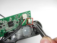
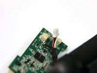
  5. Logitech Webcam Pro 9000 Motherboard Replacement, USB Connection: 手順 5、 2の画像 1 Logitech Webcam Pro 9000 Motherboard Replacement, USB Connection: 手順 5、 2の画像 2
    • Use tweezers to grasp the white wire connector on the back of the motherboard.

    • Wiggle the connector back and forth to remove it from the socket.

  6. Logitech Webcam Pro 9000 Motherboard Replacement: 手順 6、 2の画像 1 Logitech Webcam Pro 9000 Motherboard Replacement: 手順 6、 2の画像 2
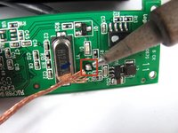
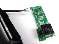
    • Desolder the joint on the front of the motherboard to completely detach the USB cable.

    • Follow this link to learn how to properly solder and desolder your parts.

  7. Logitech Webcam Pro 9000 Motherboard Replacement, Camera: 手順 7、 1の画像 1
    • Remove the two 8mm Phillips#0 screws on the back of the motherboard.

  8. Logitech Webcam Pro 9000 Motherboard Replacement: 手順 8、 3の画像 1 Logitech Webcam Pro 9000 Motherboard Replacement: 手順 8、 3の画像 2 Logitech Webcam Pro 9000 Motherboard Replacement: 手順 8、 3の画像 3
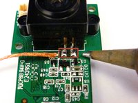
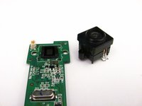
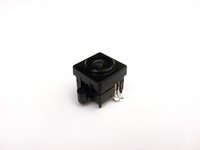
    • Remove the camera from the motherboard by desoldering the two connections as shown.

    • Follow this link to learn how to properly solder and desolder your parts.

終わりに

To reassemble your device, follow these instructions in reverse order.

ある他の人がこのガイドを完成しました。

作成者

7人の作成者と共同で作成されました。

Cory Davis

メンバー登録日: 04/14/13

236 ポイント

4のガイドは作成済み

チーム

Cal Poly, Team 12-34, Amido Spring 2013 Cal Poly, Team 12-34, Amido Spring 2013人のメンバー

CPSU-AMIDO-S13S12G34

4 メンバー

16のガイドは作成済み

0 件のコメント

コメントを追加

統計データ:

過去 24時間: 3

過去 7 日: 4

過去 30 日: 11

今までの合計 2,071