Use the plastic opening tool to pry the back cover off. Insert the tool between the back cover and red mid section and go around the entire phone.
The plastic side buttons fall out when you take the back cover off.
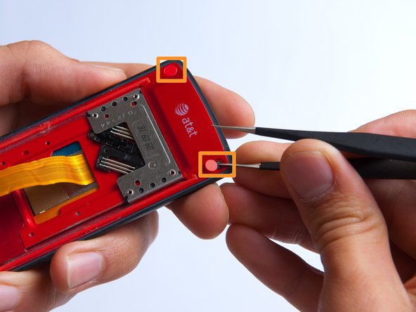
The back cover is connected to the speaker by red and black wires.
Use the tweezers to remove the red and black wires connecting the speaker to the green motherboard by pinching the sides of the plastic base near the motherboard.
Set the back cover with the speaker aside.
Use the plastic opening tool to gently lift the snapped-in motherboard from the front panel.
An orange ribbon from the LCD is connected to the underside of the motherboard, so do not force the motherboard from the rest of the phone yet.
With the plastic opening tool, gently pry the LCD connector from the motherboard.
Set the motherboard aside.
Pry the red sliding backing from the front cover by inserting the plastic opening tool in between the two sections and going around the entire phone.
Set the red sliding backing and front cover to the side.
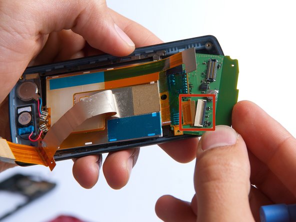
At this point, an orange ribbon is still connected to the white and black Zero Insertion Force (ZIF) connector on the keypad board. Be careful to not damage the ribbon.
Use tweezers to carefully pry up the black retainer on the connector.
If you have never soldered before, or need a refresher, take a look at iFixit's soldering guide before starting this step.
Use a soldering iron and a solder wick to de-solder the 4 wires connected to the LCD screen.
The LCD screen can easily be removed at this point by lifting it from the phone casing.
このガイドを埋め込む
サイズを選択し、以下のコードをコピーして、このガイドを小さなウィジェットとしてサイト/フォーラムに埋め込みます。
1つの手順
全ガイド
小サイズ - 600px
中サイズ - 800px
大サイズ - 1200px
プレビュー