メインコンテンツにスキップ

Insignia NS-B4111 Speaker Replacement

必要な工具と部品

  1. Insignia NS-B4111 Speaker Replacement, Battery: 手順 1、 2の画像 1 Insignia NS-B4111 Speaker Replacement, Battery: 手順 1、 2の画像 2
    • Unplug and remove the power cord. Turn the boombox upside down.

    • Grip the sides of the case and use your thumbs to pop open the battery cover.

  2. Insignia NS-B4111 Speaker Replacement: 手順 2、 2の画像 1 Insignia NS-B4111 Speaker Replacement: 手順 2、 2の画像 2
    • Pry out the batteries with your fingers.

  3. Insignia NS-B4111 Speaker Replacement, Casing: 手順 3、 1の画像 1
    • Turn the boombox upside down again. With the Phillips PH1 or the Flathead #3 screwdriver, remove the three 14mm black screws.

    • Remove the four 18mm chrome screws with the Phillips PH1 screwdriver.

  4. Insignia NS-B4111 Speaker Replacement: 手順 4、 2の画像 1 Insignia NS-B4111 Speaker Replacement: 手順 4、 2の画像 2
    • Gently remove the bottom half of the casing from the top half of the casing.

    • The antenna base is connected to the motherboard by a red wire. This wire will prevent the two halves from separating completely.

  5. Insignia NS-B4111 Speaker Replacement, Antenna Base: 手順 5、 2の画像 1 Insignia NS-B4111 Speaker Replacement, Antenna Base: 手順 5、 2の画像 2
    • Remove the 10mm chrome screw from the antenna base with the Phillips PH1 screwdriver. Remove the antenna base from the casing.

    • This red wire will now be loose and you can move it out of the antenna base slot.

  6. Insignia NS-B4111 Speaker Replacement, Motherboard: 手順 6、 1の画像 1
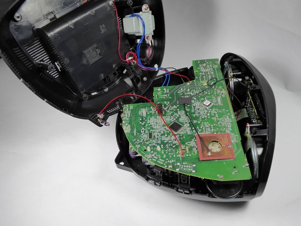
    • Unscrew the four 12.5mm screws with the Phillips PH1 Screwdriver.

    • Unscrew the one 10mm long screw with the Phillips PH1 Screwdriver.

  7. Insignia NS-B4111 Speaker Replacement: 手順 7、 1の画像 1
    • Orient the device so that the back is facing you.

    • Unplug the six pin male/female header from its socket on the motherboard. The wires on the header are these colors: burgundy, red, orange, yellow, green, and blue.

    • Use a tweezer if you find it hard to pull the header out with your fingers.

    • Gently pull out the ribbon cable from its socket on the motherboard.

    • Pay attention to the orientation of the header and the ribbon cable. Replacing the wires the wrong way may short circuit the board.

  8. Insignia NS-B4111 Speaker Replacement: 手順 8、 1の画像 1
    • Rotate the device so that the front is facing you.

    • Unplug the four pin header from its socket on the motherboard. The wires on the header are these colors: brown, red, orange, and yellow.

    • Use a tweezer if you find it hard to pull this header out with your fingers.

    • Gently pull out the ribbon cable from its socket.

    • Pay attention to the orientation of the header and the ribbon cable. Replacing the base the wrong way may short circuit the board.

  9. Insignia NS-B4111 Speaker Replacement: 手順 9、 1の画像 1
    • Pull out the two pin header from its socket on the motherboard. The wires on this header are black and white.

    • Use a tweezer if you find it hard to pull this cable out with your fingers.

  10. Insignia NS-B4111 Speaker Replacement, Front Panel: 手順 10、 1の画像 1
    • Remove the four 8.5mm chrome screws from the front panel with the Phillips PH1 screwdriver.

  11. Insignia NS-B4111 Speaker Replacement: 手順 11、 1の画像 1
    • Remove the front panel from the top casing.

  12. Insignia NS-B4111 Speaker Replacement, Speaker: 手順 12、 1の画像 1
    • The following instructions will show you how to replace the left speaker. Follow the same instructions to replace the right speaker.

    • Use the blue opening tool to scrape the red adhesive off of the 12mm chrome screw.

  13. Insignia NS-B4111 Speaker Replacement: 手順 13、 1の画像 1
    • Remove the 12mm chrome screw from the speaker with the Phillips PH1 screwdriver.

  14. Insignia NS-B4111 Speaker Replacement: 手順 14、 1の画像 1
    • Remove any glue on the edges of the speaker.

  15. Insignia NS-B4111 Speaker Replacement: 手順 15、 1の画像 1
    • Pop out the speaker from the front panel.

  16. Insignia NS-B4111 Speaker Replacement: 手順 16、 2の画像 1 Insignia NS-B4111 Speaker Replacement: 手順 16、 2の画像 2
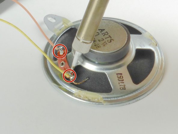
    • Unsolder the two wires at the given points. If you need help soldering, see this guide.

    • The speaker has two colored wires attached to the orange plate: one attached to the positive (+) end, and the other attached to the negative (-) end.

    • The left speaker (shown) has a yellow wire on the positive (+) end, and an orange wire on the negative (-) end.

    • The right speaker (not shown) has a brown wire on the positive (+) end, and a red wire on the negative (-) end.

終わりに

To reassemble your device, follow these instructions in reverse order.

作成者

4人の作成者と共同で作成されました。

Kristin Yoshioka

メンバー登録日: 09/21/16

984 ポイント

9のガイドは作成済み

チーム

UC Davis, Team 1-5, Oliver Fall 2016 UC Davis, Team 1-5, Oliver Fall 2016人のメンバー

UCD-OLIVER-F16S1G5

5 メンバー

11のガイドは作成済み

0 件のコメント

コメントを追加

統計データ:

過去 24時間: 0

過去 7 日: 2

過去 30 日: 5

今までの合計 521