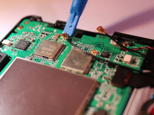
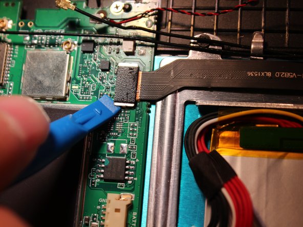
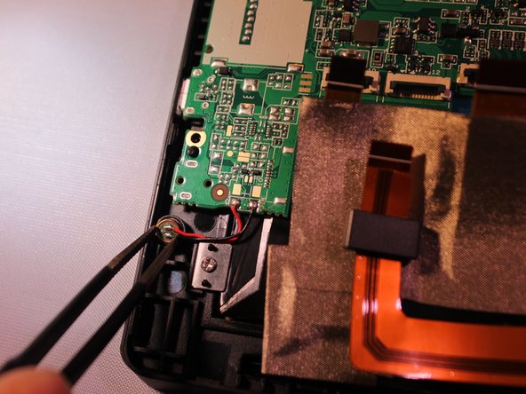
メインコンテンツにスキップ

Insignia Flex 11.6 Motherboard Replacement

必要な工具と部品

  1. Insignia Flex 11.6 Motherboard Replacement, Power Removal: 手順 1、 3の画像 1 Insignia Flex 11.6 Motherboard Replacement, Power Removal: 手順 1、 3の画像 2 Insignia Flex 11.6 Motherboard Replacement, Power Removal: 手順 1、 3の画像 3
    • Before working on the device, make sure the device is off and not plugged into any power source for safety reasons. Failure to comply could result in injury.

    • Place the device on a firm surface with the device screen facing down.

  2. Insignia Flex 11.6 Motherboard Replacement: 手順 2、 2の画像 1 Insignia Flex 11.6 Motherboard Replacement: 手順 2、 2の画像 2
  3. Insignia Flex 11.6 Motherboard Replacement: 手順 3、 3の画像 1 Insignia Flex 11.6 Motherboard Replacement: 手順 3、 3の画像 2 Insignia Flex 11.6 Motherboard Replacement: 手順 3、 3の画像 3
    この手順で使用する道具:
    Plastic Cards
    $2.99
    購入する
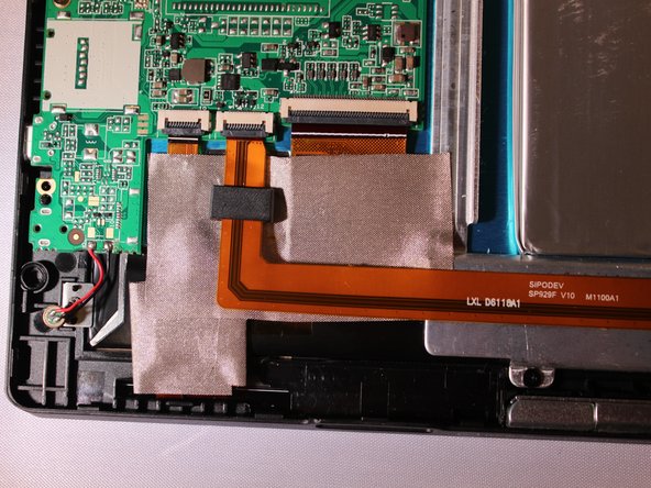
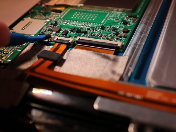
    • Using a plastic tool and the plastic card, gently pry off the back cover.

  4. Insignia Flex 11.6 Motherboard Replacement: 手順 4、 3の画像 1 Insignia Flex 11.6 Motherboard Replacement: 手順 4、 3の画像 2 Insignia Flex 11.6 Motherboard Replacement: 手順 4、 3の画像 3
    • Using tweezers, remove the electrical connector that connects to the battery to remove the power to the battery.

  5. Insignia Flex 11.6 Motherboard Replacement, Motherboard: 手順 5、 1の画像 1
    • Unplug the 2 speaker's connection from the motherboard.

  6. Insignia Flex 11.6 Motherboard Replacement: 手順 6、 2の画像 1 Insignia Flex 11.6 Motherboard Replacement: 手順 6、 2の画像 2
    • Peel the yellow tape off from on top of the electrical connectors.

  7. Insignia Flex 11.6 Motherboard Replacement: 手順 7、 2の画像 1 Insignia Flex 11.6 Motherboard Replacement: 手順 7、 2の画像 2
    • Flip up the black cover pieces to expose the 3 electrical connectors.

    • Remove 3 electrical connectors by gently pulling back on them with some tweezers.

  8. Insignia Flex 11.6 Motherboard Replacement: 手順 8、 3の画像 1 Insignia Flex 11.6 Motherboard Replacement: 手順 8、 3の画像 2 Insignia Flex 11.6 Motherboard Replacement: 手順 8、 3の画像 3
    • Unplug the 2 black ground wires from the motherboard by gently prying on them until they unhook from the motherboard.

    • Remove the black camera connector by gently prying on it until it unhooks.

  9. Insignia Flex 11.6 Motherboard Replacement: 手順 9、 2の画像 1 Insignia Flex 11.6 Motherboard Replacement: 手順 9、 2の画像 2
    • Using tweezers, remove the microphone from the the plastic cover.

  10. Insignia Flex 11.6 Motherboard Replacement: 手順 10、 1の画像 1
    • Remove 5 - 3.4 mm Phillips J000 screws from the motherboard.

    • Motherboard pops out.

終わりに

To reassemble your device, follow these instructions in reverse order.

2 の人々がこのガイドを完成させました。

作成者

3人の作成者と共同で作成されました。

Connor Sweeney

メンバー登録日: 09/28/16

449 ポイント

5のガイドは作成済み

チーム

Eastern Washington University, Team 2-4, Mathisen Fall 2016 Eastern Washington University, Team 2-4, Mathisen Fall 2016人のメンバー

EWU-MATHISEN-F16S2G4

4 メンバー

10のガイドは作成済み

2 件のコメント

This looks great. Can you provide more detail on Step 3 (opening the case?) Are there locking tabs that I need to worry about breaking? And if so, how many? Does the cover simply snap back into place?

I need to open my unit simply to disconnect the power to clear the BIOS. I stupidly disabled my USB ports and there is no way to navigate the BIOS without the (USB) keyboard (how freaking dumb is that!)

Mugsys RapSheet - 返信

Very nicely done. Do you suppose that the SSD can be upgraded to something larger?

Curtiss Riedel - 返信

コメントを追加

統計データ:

過去 24時間: 0

過去 7 日: 1

過去 30 日: 4

今までの合計 2,458