メインコンテンツにスキップ

Insignia Flex 10.1 Microphone Replacement

必要な工具と部品

  1. Insignia Flex 10.1 Microphone Replacement, Microphone: 手順 1、 1の画像 1
    • Please be aware that removing the rear panel from the back of the Flex 10.1 may cause damage to the rear panel.

  2. Insignia Flex 10.1 Microphone Replacement: 手順 2、 2の画像 1 Insignia Flex 10.1 Microphone Replacement: 手順 2、 2の画像 2
    • The rear panel is secured to the front case by 26 clips attached to the rear panel. These clips lock onto small tabs machined into the front case.

    • To free the tabs, they must be pushed toward the center of the device. When using the plastic opening tool to free the rear panel, be sure to work the tool at the location of these clips.

    • To help in visualization, the 9 clips boxed in red are located on the same side as the volume buttons.

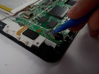
    • Remove back cover by inserting a plastic opening tool along the edge of the device to release the clips.

  3. Insignia Flex 10.1 Microphone Replacement: 手順 3、 1の画像 1
    • Opening the Flex 10.1 can be challenging. Don't get discouraged if it takes multiple attempts before the Flex 10.1 is opened.

    • Insert the plastic opening tool into the seam between the front case and the rear panel of the Flex 10.1.

    • Gently enlarge the existing gap by pressing and wiggling the plastic opening tool into the gap near each of the clips attached to the rear case, pushing the clips toward the center of the device until the clips have been freed.

    • Repeat the same procedure to free all clips around the Flex 10.1.

  4. Insignia Flex 10.1 Microphone Replacement: 手順 4、 1の画像 1
    • After ensuring all clips are free, separate the two halves of the Flex 10.1.

    • The rear panel is now free from the Flex 10.1.

  5. Insignia Flex 10.1 Microphone Replacement: 手順 5、 1の画像 1
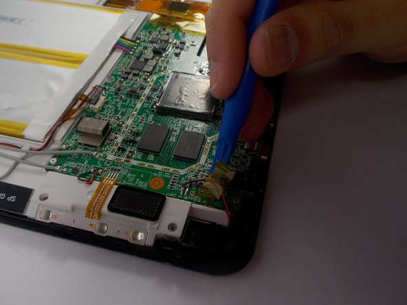
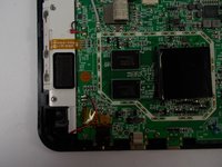
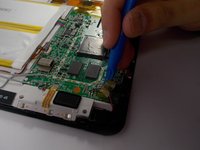
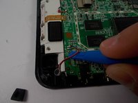
    • With the rear panel removed, the back side of the Flex 10.1 should look like this.

  6. Insignia Flex 10.1 Microphone Replacement: 手順 6、 3の画像 1 Insignia Flex 10.1 Microphone Replacement: 手順 6、 3の画像 2 Insignia Flex 10.1 Microphone Replacement: 手順 6、 3の画像 3
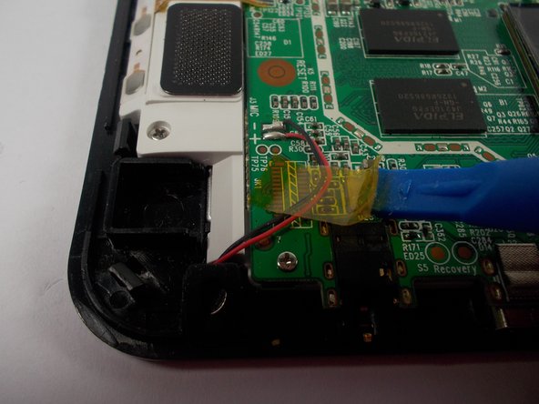
    • Using the plastic opening tool or your fingers, remove the tape holding the black and red wires down.

    • The motherboard is a sensitive area of the device, so be careful to not scratch it when removing the tape.

  7. Insignia Flex 10.1 Microphone Replacement: 手順 7、 3の画像 1 Insignia Flex 10.1 Microphone Replacement: 手順 7、 3の画像 2 Insignia Flex 10.1 Microphone Replacement: 手順 7、 3の画像 3
    • Gently remove microphone cover by holding the wire and pulling the cover off.

    • The microphone is enclosed by a black silicone cover.

  8. Insignia Flex 10.1 Microphone Replacement: 手順 8、 2の画像 1 Insignia Flex 10.1 Microphone Replacement: 手順 8、 2の画像 2
    • The next few steps require a soldering iron.

    • Those who are new to soldering may want to check out iFixit's soldering technique guide. はんだ付けとはんだ除去の作業ガイド.

    • Due to the fragile nature of electronic components, it is important to limit the amount of heat transferred from the soldering iron to the motherboard. A simple way to accomplish this is to pull the two wires with gentle continuous tension while the soldering iron heats up the connection.

    • The microphone is connected to the motherboard by a red and black wire.

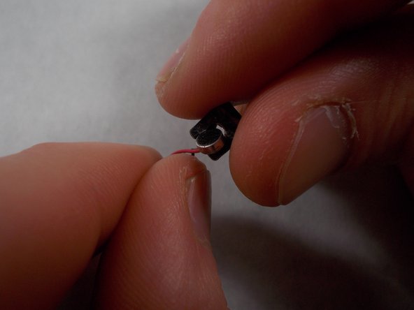
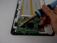
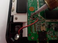
    • Begin by heating up the two solder joints on the motherboard one at a time.

    • When the solder melts and the wire is free from the motherboard, immediately lift the solder tip off the connection to avoid damage.

  9. Insignia Flex 10.1 Microphone Replacement: 手順 9、 1の画像 1
    • The microphone is now free from the motherboard.

  10. Insignia Flex 10.1 Microphone Replacement: 手順 10、 1の画像 1
    • Solder the replacement microphone to the same joints on the motherboard.

    • Solder the connection by momentarily placing the tip of the soldering iron against the connection, pressing solder into the connection (melting it), and quickly removing both the solder and the tip of the soldering iron from the connection. The solder should flow around the wire and motherboard for a successful connection.

    • The black wire must be soldered to the negative joint.

    • The red wire must be soldered to the positive joint.

    • The positive and negative signs are indicated on the motherboard as well as in the picture.

終わりに

To reassemble your device, follow these instructions in reverse order.

作成者

3人の作成者と共同で作成されました。

Richard

メンバー登録日: 03/23/16

455 ポイント

1ガイドが承認済み

チーム

UMass Dartmouth, Team 2-1, Isaacson Spring 2016 UMass Dartmouth, Team 2-1, Isaacson Spring 2016人のメンバー

UMASSD-ISAACSON-S16S2G1

3 メンバー

11のガイドは作成済み

0 件のコメント

コメントを追加

統計データ:

過去 24時間: 0

過去 7 日: 1

過去 30 日: 7

今までの合計 516