メインコンテンツにスキップ

HyperX Alloy Origins Key Switch LED Replacement

必要な工具と部品

  1. HyperX Alloy Origins Key Switch LED Replacement, Toggle Indicator Tab: 手順 1、 1の画像 1
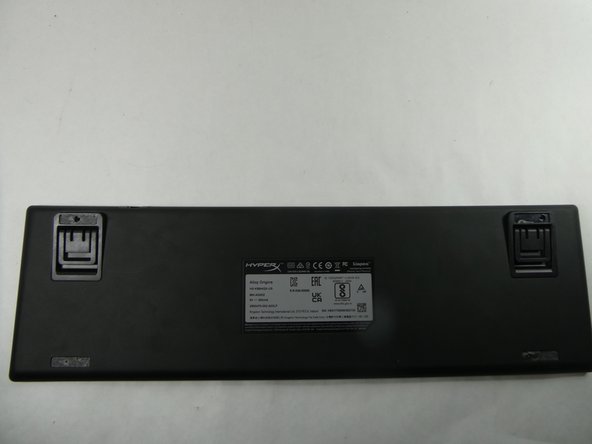
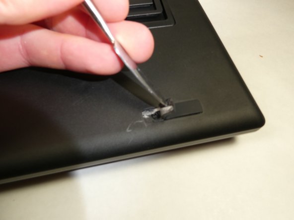
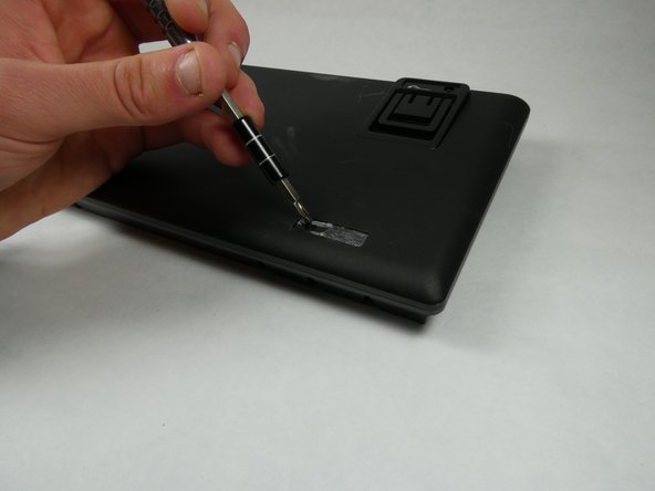
    • Locate the toggle indicator tab on the top right corner of the keyboard.

  2. HyperX Alloy Origins Key Switch LED Replacement: 手順 2、 2の画像 1 HyperX Alloy Origins Key Switch LED Replacement: 手順 2、 2の画像 2
    • Insert the metal spudger or some other separating instrument into the right crevasse between the tab and the keyboard.

    • Lift up gently on the tab, while holding the left side of the tab down.

    • The tab can spring upwards upon removal. Eye protection is recommended during this step.

  3. HyperX Alloy Origins Key Switch LED Replacement, Backplate: 手順 3、 2の画像 1 HyperX Alloy Origins Key Switch LED Replacement, Backplate: 手順 3、 2の画像 2
    • Flip the keyboard over so that the backplate is facing you.

  4. HyperX Alloy Origins Key Switch LED Replacement: 手順 4、 3の画像 1 HyperX Alloy Origins Key Switch LED Replacement: 手順 4、 3の画像 2 HyperX Alloy Origins Key Switch LED Replacement: 手順 4、 3の画像 3
    • Remove the rubber feet on the four corners of the backplate.

    • When reassembling, use an adhesive to reattach the feet. A silicone rubber adhesive is recommended.

  5. HyperX Alloy Origins Key Switch LED Replacement: 手順 5、 3の画像 1 HyperX Alloy Origins Key Switch LED Replacement: 手順 5、 3の画像 2 HyperX Alloy Origins Key Switch LED Replacement: 手順 5、 3の画像 3
    • Remove the specified keycaps as depicted in the image.

  6. HyperX Alloy Origins Key Switch LED Replacement: 手順 6、 3の画像 1 HyperX Alloy Origins Key Switch LED Replacement: 手順 6、 3の画像 2 HyperX Alloy Origins Key Switch LED Replacement: 手順 6、 3の画像 3
    • Remove all Philips #0 screws from the new openings created after removing the rubber feet and plastic tab.

  7. HyperX Alloy Origins Key Switch LED Replacement: 手順 7、 3の画像 1 HyperX Alloy Origins Key Switch LED Replacement: 手順 7、 3の画像 2 HyperX Alloy Origins Key Switch LED Replacement: 手順 7、 3の画像 3
    • Separate the backplate from the keyboard using your hands.

  8. HyperX Alloy Origins Key Switch LED Replacement, Key Switch: 手順 8、 3の画像 1 HyperX Alloy Origins Key Switch LED Replacement, Key Switch: 手順 8、 3の画像 2 HyperX Alloy Origins Key Switch LED Replacement, Key Switch: 手順 8、 3の画像 3
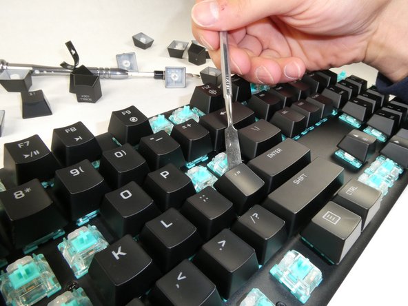
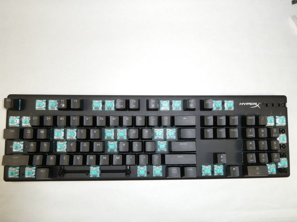
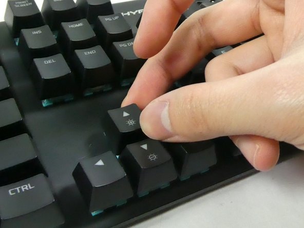
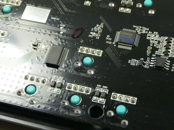
    • Identify the key switch to be replaced.

    • Remove its keycap by carefully prying it off of the keyboard with your fingers.

  9. HyperX Alloy Origins Key Switch LED Replacement: 手順 9、 2の画像 1 HyperX Alloy Origins Key Switch LED Replacement: 手順 9、 2の画像 2
    • Flip the keyboard over to face the PCB.

    • Identify the corresponding switch to be removed.

  10. HyperX Alloy Origins Key Switch LED Replacement: 手順 10、 1の画像 1
    • Plug in and turn on your soldering iron.

    • Do not touch the metal end of the soldering iron while it is powered on. Allow the soldering iron to cool before stowing it away.

  11. HyperX Alloy Origins Key Switch LED Replacement: 手順 11、 3の画像 1 HyperX Alloy Origins Key Switch LED Replacement: 手順 11、 3の画像 2 HyperX Alloy Origins Key Switch LED Replacement: 手順 11、 3の画像 3
    この手順で使用する道具:
    Desoldering Pump
    $3.99
    購入する
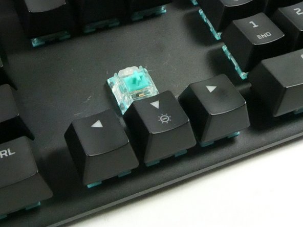
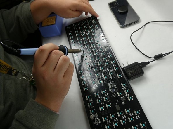
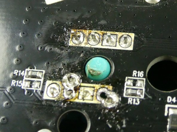
    • Melt the solder surrounding the four pins of the switch's LED, and the two lower pins of the switch body.

    • To remove the melted solder, use a desoldering iron, a desoldering pump, or desoldering braid.

    • The exposed switch pins are susceptible to damage from the soldering iron. Avoid applying heavy pressure to mitigate pin bending.

  12. HyperX Alloy Origins Key Switch LED Replacement: 手順 12、 1の画像 1
    • Using a spudger or another metallic instrument, firmly press down upon the exposed plastic of the switch. This will separate the switch from the rest of the keyboard.

    • If the switch's pins will not separate from the keyboard's PCB, continue applying the soldering iron to the pins to melt any residual solder.

  13. HyperX Alloy Origins Key Switch LED Replacement, Key Switch LED: 手順 13、 1の画像 1
    • Gently pull the LED off of the switch.

    • Do not break the LED pins while it is still attached to the switch.

終わりに

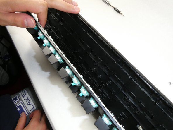
To reassemble your device, follow these instructions in reverse order. Note that when reattaching the switch back to the keyboard PCB, the switch needs to be held in place behind the keyboard while soldering.

作成者

2人の作成者と共同で作成されました。

Adam Sles

メンバー登録日: 10/25/22

247 ポイント

2のガイドは作成済み

チーム

UMass Dartmouth, Team 5-2, Sinclaire Fall 2022 UMass Dartmouth, Team 5-2, Sinclaire Fall 2022人のメンバー

UMASSD-SINCLAIRE-F22S5G2

5 メンバー

15のガイドは作成済み

0 件のコメント

コメントを追加

統計データ:

過去 24時間: 6

過去 7 日: 27

過去 30 日: 153

今までの合計 3,592