メインコンテンツにスキップ

HP Chromebook 11A G6 EE Motherboard Replacement

必要な工具と部品

  1. HP Chromebook 11A G6 EE Motherboard Replacement, Motherboard: 手順 1、 3の画像 1 HP Chromebook 11A G6 EE Motherboard Replacement, Motherboard: 手順 1、 3の画像 2 HP Chromebook 11A G6 EE Motherboard Replacement, Motherboard: 手順 1、 3の画像 3
    • Remove six 6.6 mm screws from the back case using a Phillips #1 screwdriver.

    • Remove two 8.7 mm screws from the back case using a Phillips #1 screwdriver.

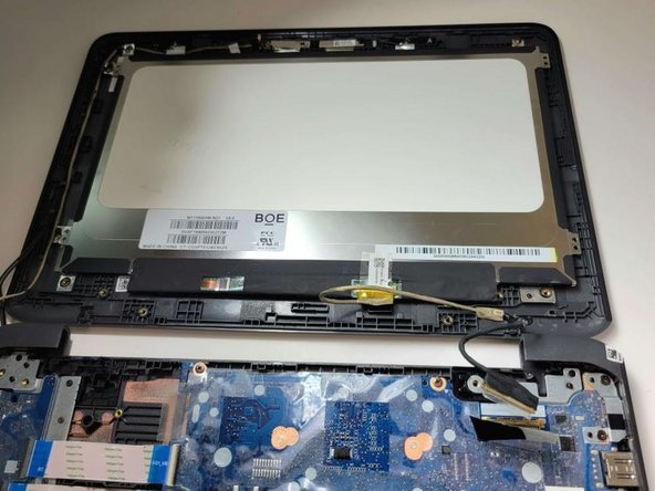
    • Turn the computer over and open it as if you are going to use it.

  2. HP Chromebook 11A G6 EE Motherboard Replacement: 手順 2、 3の画像 1 HP Chromebook 11A G6 EE Motherboard Replacement: 手順 2、 3の画像 2 HP Chromebook 11A G6 EE Motherboard Replacement: 手順 2、 3の画像 3
    • Use the iFixit opening tool to get between the keyboard bezel and the outer edge of the laptop.

    • There are several clips on all sides that will need to be released. You'll hear and feel a pop as each clip is released.

    • Move the opening tool or spudger around the perimeter until you unclipped the keyboard on all sides.

    • This will require a little force. The only thing you don't want to do is push the spudger too deep under the keyboard. You could damage the internals if you do.

  3. HP Chromebook 11A G6 EE Motherboard Replacement: 手順 3、 2の画像 1 HP Chromebook 11A G6 EE Motherboard Replacement: 手順 3、 2の画像 2
    • Carefully lift the top of the keyboard up to access the ribbon cables connecting it to the device.

    • Use the tip of a spudger or your fingernail to flip up the small locking flap on each connector. Then, pull the cables out.

    • Lift the keyboard off the to remove.

  4. HP Chromebook 11A G6 EE Motherboard Replacement: 手順 4、 1の画像 1
    • Use a Phillips #1 screwdriver to remove the 2.5 mm screw connected to the wireless module.

    • Gently peel back the tape and slide the wireless module out.

    • Take careful note of the routing of the wires from the display panel to the wireless module.

  5. HP Chromebook 11A G6 EE Motherboard Replacement: 手順 5、 1の画像 1
    • Peel back the tape that secures the webcam to the left display panel hinge.

    • Gently slide out the webcam connector.

    • Take note of the routing of the webcam connector cable.

  6. HP Chromebook 11A G6 EE Motherboard Replacement: 手順 6、 3の画像 1 HP Chromebook 11A G6 EE Motherboard Replacement: 手順 6、 3の画像 2 HP Chromebook 11A G6 EE Motherboard Replacement: 手順 6、 3の画像 3
    • Release the tape that secures the battery cable connector to the system board.

    • Disconnect the battery cable from the system board. Pull the cable straight out of the connector by the white plastic portion near the connection point.

    • Don't pull the cable out by the wire or it may become damaged.

  7. HP Chromebook 11A G6 EE Motherboard Replacement: 手順 7、 2の画像 1 HP Chromebook 11A G6 EE Motherboard Replacement: 手順 7、 2の画像 2
    • Peel the tape off of the speaker cable connector.

    • Disconnect the speaker cable from the system board. Pull the cable straight out of the connector by the black plastic portion near the connection point. Disconnect the speaker cable from the system board.

    • To avoid damage, don't pull on the wires.

  8. HP Chromebook 11A G6 EE Motherboard Replacement: 手順 8、 3の画像 1 HP Chromebook 11A G6 EE Motherboard Replacement: 手順 8、 3の画像 2 HP Chromebook 11A G6 EE Motherboard Replacement: 手順 8、 3の画像 3
    • Peel back retention tape.

    • Use pry tool carefully to disconnect LCD cable from motherboard. Lift up on the back arm of the connection cable.

    • Be careful when removing connection, mishandling can cause serious damage to your notebook.

  9. HP Chromebook 11A G6 EE Motherboard Replacement: 手順 9、 2の画像 1 HP Chromebook 11A G6 EE Motherboard Replacement: 手順 9、 2の画像 2
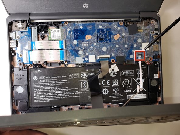
    • Remove the 5 M2x3.5 PH1 screws from motherboard.

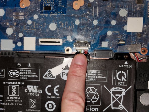
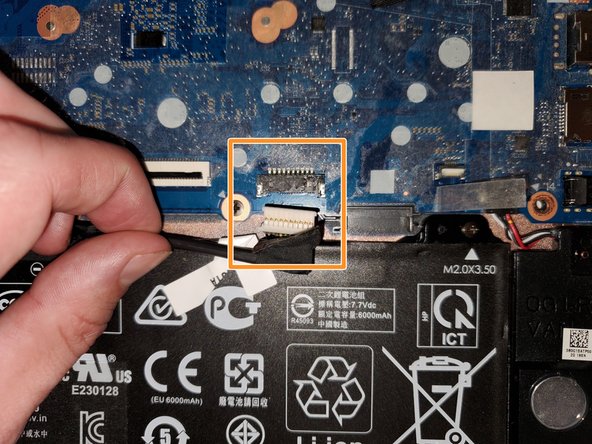
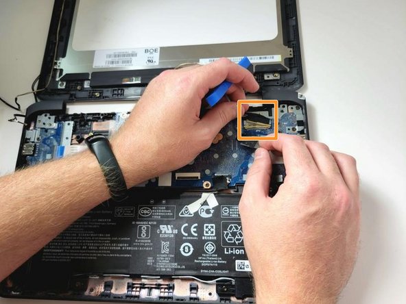
    • Peel back protective tape, lift up on the back arm of the ZIF connector cable. Use prytool very carefully if needed to remove connectors.

    • Very little to no force should be required to remove connectors if done correctly.

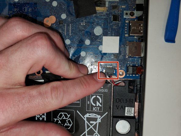
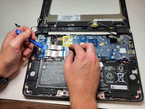
    • Once screws are out, peel back the protective tape at the Wifi card socket. Carefully place finger on/under socket card connection area for leverage.

    • Make sure no cables are under motherboard when replacing and putting back together.

    • Be careful when removing connections as mishandling can cause serious damage to your notebook.

終わりに

To reassemble your device, follow these instructions in reverse order.

ある他の人がこのガイドを完成しました。

作成者

3人の作成者と共同で作成されました。

Scott

メンバー登録日: 09/06/23

365 ポイント

2のガイドは作成済み

チーム

Austin Community College, Team 8-1, Watkins Fall 2023 Austin Community College, Team 8-1, Watkins Fall 2023人のメンバー

AUSTINCC-WATKINS-F23S8G1

3 メンバー

5のガイドは作成済み

0 件のコメント

コメントを追加

統計データ:

過去 24時間: 0

過去 7 日: 3

過去 30 日: 7

今までの合計 87