メインコンテンツにスキップ

Fix a motherboard with failed NVIDIA graphics chip

必要な工具と部品

  1. Fix a motherboard with failed NVIDIA graphics chip, Battery: 手順 1、 3の画像 1 Fix a motherboard with failed NVIDIA graphics chip, Battery: 手順 1、 3の画像 2 Fix a motherboard with failed NVIDIA graphics chip, Battery: 手順 1、 3の画像 3
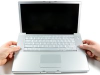
    • Use your fingers to push both battery release tabs away from the battery, and lift the battery out of the computer.

  2. Fix a motherboard with failed NVIDIA graphics chip, RAM Shield: 手順 2、 2の画像 1 Fix a motherboard with failed NVIDIA graphics chip, RAM Shield: 手順 2、 2の画像 2
    • Remove the three identical 2mm Phillips screws from the memory door.

    • Lift the memory door up enough to grip it and slide it toward you, pulling it away from the casing.

  3. Fix a motherboard with failed NVIDIA graphics chip, Upper Case: 手順 3、 1の画像 1
    • Remove the two 2.8 mm Phillips screws in the battery compartment near the latch.

  4. Fix a motherboard with failed NVIDIA graphics chip: 手順 4、 1の画像 1
    • Remove the following 6 screws:

    • Two 10 mm T6 Torx screws on either side of the RAM slot.

    • Four 14.5 mm Phillips screws along the hinge.

  5. Fix a motherboard with failed NVIDIA graphics chip: 手順 5、 1の画像 1
    • Remove the four 3.2 mm PH00 Phillips screws on the port side of the computer.

  6. Fix a motherboard with failed NVIDIA graphics chip: 手順 6、 1の画像 1
    • Rotate the computer 90 degrees and remove the two 3.2 mm Phillips screws from the rear of the computer.

  7. Fix a motherboard with failed NVIDIA graphics chip: 手順 7、 1の画像 1
    • Rotate the computer 90 degrees again and remove the four 3.2 mm Phillips screws from the side of the computer.

  8. Fix a motherboard with failed NVIDIA graphics chip: 手順 8、 3の画像 1 Fix a motherboard with failed NVIDIA graphics chip: 手順 8、 3の画像 2 Fix a motherboard with failed NVIDIA graphics chip: 手順 8、 3の画像 3
    • Do not yank the upper case off quickly. The case is attached to the logic board via a ribbon cable.

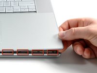
    • Lift up at the rear of the case and work your fingers along the sides, freeing the case as you go. Once you have freed the sides, you may need to rock the case up and down to free the front of the upper case.

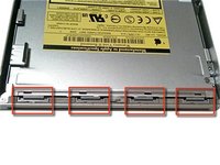
    • There are four plastic clips above the DVD slot, and another above and to the left of the IR sensor. These clips can be very difficult to disengage without prying. They can also be difficult to re-engage during reassembly.

    • Reassembly Tip: Press down firmly on the tip of the top case above the location of each clip until you hear a snap to reseat them in their slots.

    • Reassembly Tip: The two center DVD clips will rarely snap back into place properly without help, and downward pressure will instead simply deform the frame around the DVD slot. Support the frame by inserting a plastic spudger into the DVD slot directly under the clip location until it is snug, then press down until you hear the snap.

  9. Fix a motherboard with failed NVIDIA graphics chip: 手順 9、 2の画像 1 Fix a motherboard with failed NVIDIA graphics chip: 手順 9、 2の画像 2
    • Disconnect the trackpad and keyboard ribbon cable from the logic board, removing tape as necessary.

    • Note: It is possible to replace the hard drive without disconnecting the keyboard from the chassis, but it will need to be held upright to keep it out of the way, while still allowing you both hands to work on the drive removal.

    • Be careful when removing the keyboard-trackpad ribbon cable to ensure that the rear of the upper case is disengaged from the area near the hinge. It is easy to accidentally bend the screw receivers on either side of the keyboard.

    • Remove the upper case.

  10. Fix a motherboard with failed NVIDIA graphics chip, Optical Drive: 手順 10、 1の画像 1
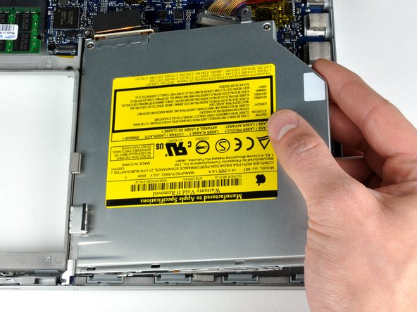
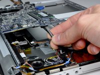
    • Use the flat end of a spudger to disconnect the orange SuperDrive ribbon cable from the logic board, removing tape as necessary.

  11. Fix a motherboard with failed NVIDIA graphics chip: 手順 11、 2の画像 1 Fix a motherboard with failed NVIDIA graphics chip: 手順 11、 2の画像 2
    • Remove the following 4 screws:

    • Two 3.3 mm silver Phillips screws on either side of the SuperDrive.

    • One 4.7 mm silver T6 Torx screw from the top left corner of the drive.

    • One 6.2 mm black Phillips screw at the top right corner of the drive.

    • Lift the optical drive up and out of the computer.

  12. Fix a motherboard with failed NVIDIA graphics chip, Logic Board: 手順 12、 1の画像 1
    • Disconnect the hard drive and ExpressCard connectors from the left side of the logic board.

  13. Fix a motherboard with failed NVIDIA graphics chip: 手順 13、 1の画像 1
    • Disconnect the iSight and display data cables from the logic board by sliding them straight back out of their connectors, removing tape as necessary.

  14. Fix a motherboard with failed NVIDIA graphics chip: 手順 14、 1の画像 1
    • Disconnect the eight indicated connectors by placing a spudger beneath the wired side of each one and lifting up.

    • Use care when disconnecting some of the smaller connectors. A forceful prod with the spudger may accidentally break them off the logic board.

  15. Fix a motherboard with failed NVIDIA graphics chip: 手順 15、 1の画像 1
    • Remove the foam bumper from the top of the right hinge of the display.

  16. Fix a motherboard with failed NVIDIA graphics chip: 手順 16、 1の画像 1
    • Remove the silver 9.5 mm T6 Torx screw securing the ground loop in the display data cable to the casing.

  17. Fix a motherboard with failed NVIDIA graphics chip: 手順 17、 1の画像 1
    • Remove the single black 6 mm T6 Torx screw securing the upper portion of the logic board to the lower case.

  18. Fix a motherboard with failed NVIDIA graphics chip: 手順 18、 1の画像 1
    • Peel up the orange Kapton tape securing the right thermal sensor cable to the logic board.

  19. Fix a motherboard with failed NVIDIA graphics chip: 手順 19、 1の画像 1
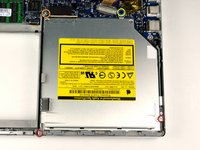
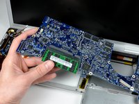
    • Remove the following 15 screws:

    • One 4.4 mm black Phillips screw to the right of the ram slot.

    • Eight 4.7 mm silver T6 Torx screws securing the logic board to the lower case.

    • If you leave the five uppermost orange screws in place, the heatsink/pipes come out effortlessly, still mounted onto the main board. That way its thermal connection is retained, and you won't need to reapply thermal paste as instructed two steps below.

    • One 6.2 mm black T6 Torx screw on the right side of the left fan.

    • Five 9.4 mm silver T6 Torx screws securing the left and right fans.

  20. Fix a motherboard with failed NVIDIA graphics chip: 手順 20、 2の画像 1 Fix a motherboard with failed NVIDIA graphics chip: 手順 20、 2の画像 2
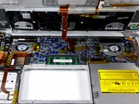
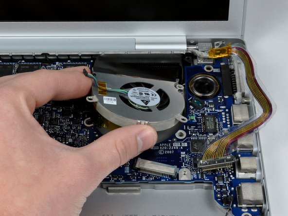
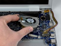
    • Hold the logic board down with one hand and use your other hand to lift the left fan up from its housing. There is a piece of black tape securing the left fan to the heat sink. Carefully peel this tape up from the heat sink as you lift the left fan up.

    • Place the left fan above the Airport card. It is not necessary to remove the fan from the computer entirely.

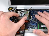
    • Lift the right fan up and carefully peel up the tape securing the fan to the heat sink as you go.

    • Remove the right fan from the computer.

  21. Fix a motherboard with failed NVIDIA graphics chip: 手順 21、 2の画像 1 Fix a motherboard with failed NVIDIA graphics chip: 手順 21、 2の画像 2
    • Lift up the left side of the logic board and disconnect the gray and black power cable from the bottom of the board.

    • Pull the power cable connector parallel to the face of the logic board.

    • Grasp the logic board at the left side and at the thin section, and rotate the logic board out of the lower case.

    • If you detached the heatsink from the motherboard two steps above, you'll have to clean off and replace the old thermal compound from the chips on the back of the logic board. Use our Applying Thermal Paste Guide to prepare the processor and heat sink surfaces.

  22. Fix a motherboard with failed NVIDIA graphics chip, Just go on with given link...: 手順 22、 2の画像 1 Fix a motherboard with failed NVIDIA graphics chip, Just go on with given link...: 手順 22、 2の画像 2
    • Thanks to http://www.laptoprepair101.com/fix-lapto...

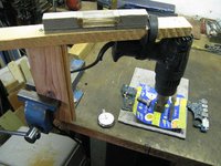
    • It fixed a MacBook Pro 15-Inch A1260 (Early 2008)

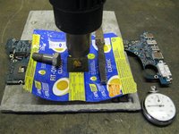
    • I have applied some liquid flux underneath the chip. Artikelnr. 472-345-30-L eclipse-dortmund.de (via Amazon)

終わりに

To reassemble your device, follow these instructions in reverse order.

作成者

1人の作成者と共同作成されました。

Pilo

メンバー登録日: 05/19/15

73 ポイント

1ガイドが承認済み

0 件のコメント

コメントを追加

統計データ:

過去 24時間: 2

過去 7 日: 10

過去 30 日: 46

今までの合計 1,225