はじめに
Use this guide to replace the display assembly, including the LCD screen, front glass and digitizer, on your Fairphone.
必要な工具と部品
-
-
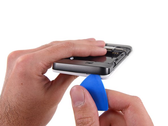
With the indentation as leverage, use your fingernail to pry the bottom portion of the back cover from the phone.
-
-
-
Use a fingernail in this indentation to push the battery toward the top of the phone
-
Pull the battery out away from the phone.
-
-
-
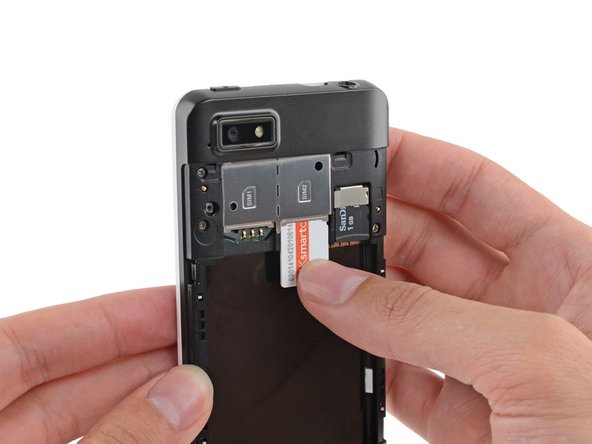
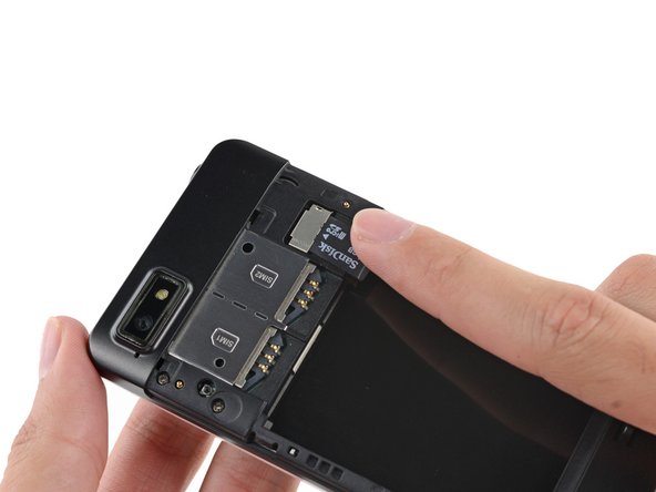
Use your finger to slide the SIM card straight down out of its tray.
-
Remove the SIM card from your Fairphone.
-
-
-
Remove the five 3.9 mm Phillips #000 screws securing the midframe to the display assembly.
-
-
-
-
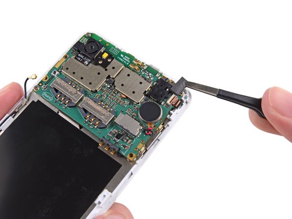
Use tweezers to remove the volume rocker and power buttons from the display assembly.
-
-
-
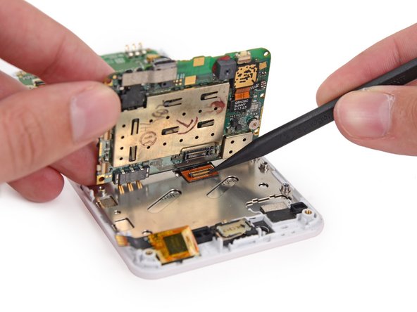
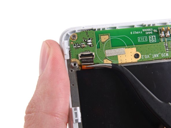
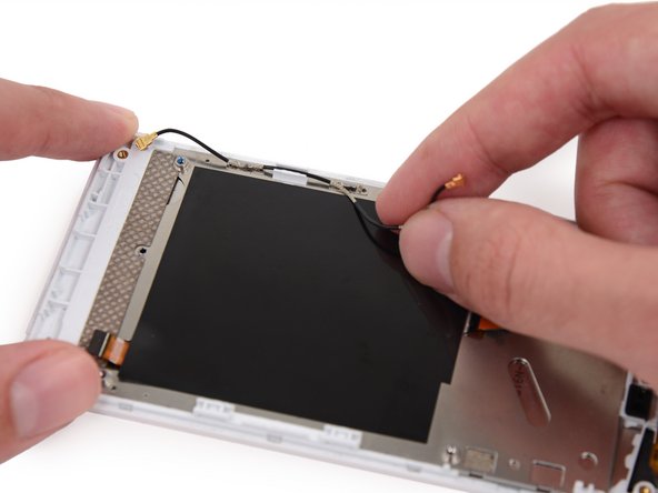
Use the flat end of a spudger to disconnect the antenna cable connector.
-
-
-
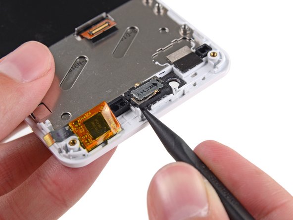
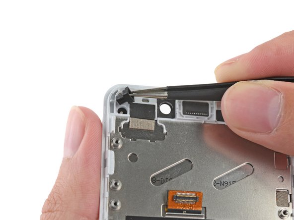
Use the tip of a spudger to gently pry the speaker up from the display assembly.
-
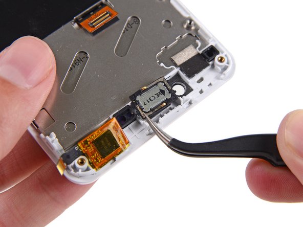
Remove the speaker.
-
-
-
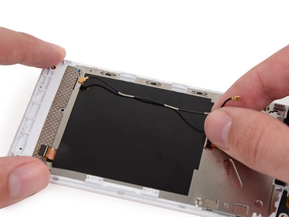
Remove the antenna interconnect cable from the display assembly.
In this step you need to replace the earpiece speaker too, follow this guide: Fairphone 1 Display Assembly Replacement
Don't forget to put two little rubber parts over the proximity sensor and the notification LED on the new display, otherwise the proximity sensor will bug out later. They are visible in the picture for Step 18.
Sadly I lost the small rubber part in front of the proximity/light sensor.
Any idea where i can get it, because I have now the bug, everytime a call comes in, the display will turn and stay black until the call is ended :-(
Thanks!
pappou -
Which parts are the proximity sensor and the notification LED?
Indeed, the rubber parts didn't came at first, and lastly also the speaker was stuck on the old phone, so this was a rather unwelcome discovery for a non-technician wanting to repair the phone. By lifting it off a small rubber joint came with it so this had to be removed before gluing it back on the new front (a protective adhesive tape needed first to be removed too so this speaker could nicely be glued on. (of course all this is written still without reassembling my phone). Erik
It worked ! I managed to get everything back in place, even after suddenly finding another small rubber thing on my table which after magnifying the pictures here, seemed to have fallen of the motherboard.
So, a part from the fact that this Dragontrail glass is not so strong as promised, I'm really happy I could repair my Fairphone myself.
-
-
-
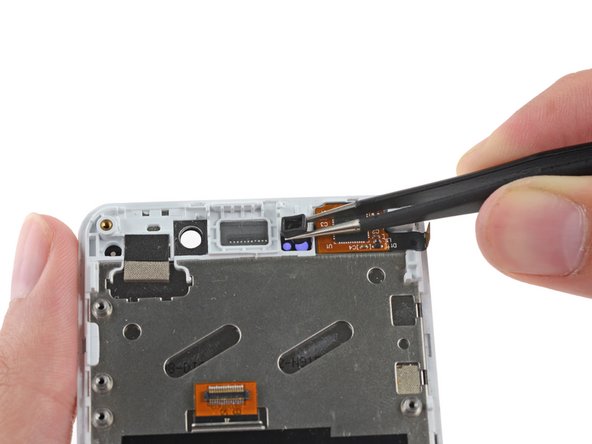
Remove the rubber guide to the right of the earpiece speaker recess.
-
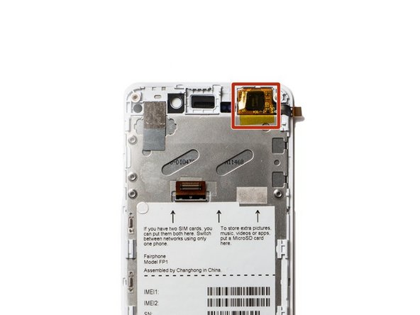
Your replacement display will have a piece of yellow tape covering the touch sensor chip. Do not remove this tape; if you do, your phone may not work after reassembly.
When putting the rubber placeholder back in place watch for the right direction. It has a bigger and a smaller hole and they must be placed in the right orientation, otherwise the proximity sensor does not work properly (display is turned off immediately when calling someone)
-


To reassemble your device, follow these instructions in reverse order.
To reassemble your device, follow these instructions in reverse order.
102 の人々がこのガイドを完成させました。

16 件のコメント
The Camera is not mentioned at all. It's glued to the Display and yet still working, it can't focus anymore. So I might have to get a new one as well.
Awesome! Did it, and everything still works. Mighty pleased with myself. Thank you, iFixit!!!
Just did it successfully. Great guide!
ouf, j'ai réussi à remplacer mon écran fissuré suite à une chute. Je suis prêt à contribuer en traduisant les parties complexes du tutoriel en français, si quelqu'un peut m'indiquer la marche à suivre pour proposer une version FR.
Plusieurs étapes sont assez complexes - stressantes (comme indiqué l'APN qui reste collé et ne se détache pas de la carte mère par ex.) mais ne requièrent aucune compétence spécifique, juste du doigté et de la patience.
En tout cas merci
salut, toi aussi tu dirais que ca prend environ une heure ?
cazeph -
Pfew!!! Done... Thanks for all the pics, comments, and instructions (Nico/France)
It works perfectly and looks like a new phone! Wow!
I also avoided step 21 and removed the wifi cable together with the board.
Hint for camera step 18: It was glued on very well. What I did was to lift the mainboard slighty and entered with a screwdriver between camera and case. Finally I saw that the metal plate came off too which you already have in your new case. But it was then much easier to remove it after the disassembly with my fingernails. To be able to do this step you have to remove the power button but I would recommend that anyway.
Great pictures and explanations!! Thank you very much! It took me about 30 minutes to do it.Happy! :-)
45 min. But camera lost autofocus :-(.
It was glued too hard so removal was difficult and probalbly damaged it…
Gert Arijs - 返信
45 min. But camera lost autofocus :-(.
It was glued too hard so removal was difficult and probalbly damaged it…
Gert Arijs - 返信