メインコンテンツにスキップ

Dynex DX‑PDVD9 Screen Replacement

必要な工具と部品

  1. Dynex DX‑PDVD9 Screen Replacement, Screen: 手順 1、 2の画像 1 Dynex DX‑PDVD9 Screen Replacement, Screen: 手順 1、 2の画像 2
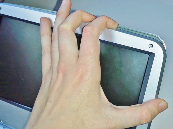
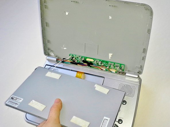
    • To remove the cover of the screen, the four rubber feet must be removed to expose four screws.

    • Lift out the rubber feet with tweezers or a spudger.

  2. Dynex DX‑PDVD9 Screen Replacement: 手順 2、 1の画像 1
    • Remove the four screws underneath the rubber feet of the device.

    • The top two screws are 3.175 mm head, 4.762 mm length flat-heat screws.

    • The bottom two screws are 4.762 mm head, 6.35 mm length flat-head screws.

  3. Dynex DX‑PDVD9 Screen Replacement: 手順 3、 2の画像 1 Dynex DX‑PDVD9 Screen Replacement: 手順 3、 2の画像 2
    • Using a plastic opening tool, lift off the screen cover from the screen and the top of the device.

    • A thin piece of tape lies between the screen case and the screen, force may be required to pull off the screen case.

  4. Dynex DX‑PDVD9 Screen Replacement: 手順 4、 3の画像 1 Dynex DX‑PDVD9 Screen Replacement: 手順 4、 3の画像 2 Dynex DX‑PDVD9 Screen Replacement: 手順 4、 3の画像 3
    • Remove the black tape connecting the wires to the front cover.

    • The tape can be removed with tweezers or your fingers.

  5. Dynex DX‑PDVD9 Screen Replacement: 手順 5、 2の画像 1 Dynex DX‑PDVD9 Screen Replacement: 手順 5、 2の画像 2
    • Remove the screen's ribbon cable by lifting the connecting flap with your fingers.

    • Gently pull out the ribbon cable with tweezers or your fingers.

    • In the second image, the connecting flap on the device is removed, however the device should contain the same connecting flap seen in the first image.

  6. Dynex DX‑PDVD9 Screen Replacement: 手順 6、 3の画像 1 Dynex DX‑PDVD9 Screen Replacement: 手順 6、 3の画像 2 Dynex DX‑PDVD9 Screen Replacement: 手順 6、 3の画像 3
    • Gently remove the screen with your hands, peeling it off of the front cover.

    • Be gentle when removing the screen, it is connected to the front cover by adhesive foam pads which require force to remove.

  7. Dynex DX‑PDVD9 Screen Replacement: 手順 7、 1の画像 1
    • Remove the black and white wires by desoldering them from the circuit board attached to the case.

    • For proper soldering and desoldering techniques reference How To Solder and Desolder Connections.

    • Soldering requires the iron to be at hot temperatures and can cause burns. Wear safety glasses as needed. Be extremely careful with the cables in this step as they could melt, burn, or break.

終わりに

To reassemble your device, follow these instructions in reverse order.

作成者

1人の作成者と共同作成されました。

Roxanne Hoffman

メンバー登録日: 04/14/14

457 ポイント

2のガイドは作成済み

チーム

Cal Poly, Team 8-10, Regan Spring 2014 Cal Poly, Team 8-10, Regan Spring 2014人のメンバー

CPSU-REGAN-S14S8G10

4 メンバー

16のガイドは作成済み

0 件のコメント

コメントを追加

統計データ:

過去 24時間: 0

過去 7 日: 0

過去 30 日: 1

今までの合計 333