メインコンテンツにスキップ

このバージョンは誤った内容を含んでいる可能性があります。最新の承認済みスナップショットに切り替えてください。

必要な工具と部品

  1. この手順は未翻訳です。 翻訳を手伝う。

    : 手順 1、 1の画像 1
    • 1. unplug laptop

    • 2. remove battery

    • 3. remove screw

    • Remove disk drive by pressing in the pull mechanism, causing it to extend outwards, then use the pull handle to pull out disk drive.

  2. この手順は未翻訳です。 翻訳を手伝う。

    : 手順 2、 1の画像 1
    • remove 2 retention screws

    • slide HD carriage out

  3. この手順は未翻訳です。 翻訳を手伝う。

    : 手順 3、 1の画像 1
    • open laptop

    • with a small screwdriver carefully pry plastic cover

    • it helps to open the laptop all the way

    • be careful not to break these clips

    • The clips found under here were specially tricky

  4. この手順は未翻訳です。 翻訳を手伝う。

    : 手順 4、 3の画像 1 : 手順 4、 3の画像 2 : 手順 4、 3の画像 3
    • remove screws X 2

    • carefully lift keyboard, being careful not to damage the flat cable.

    • lift up tab to release flat cable and remove keyboard

  5. この手順は未翻訳です。 翻訳を手伝う。

    : 手順 5、 3の画像 1 : 手順 5、 3の画像 2 : 手順 5、 3の画像 3
    • disconnect the three wires

    • disconnect video connector

    • remove ground screw

    • remove 3 screws

    • remove last screw, note this screw is longer then the other three

    • remove screen

  6. この手順は未翻訳です。 翻訳を手伝う。

    : 手順 6、 3の画像 1 : 手順 6、 3の画像 2 : 手順 6、 3の画像 3
    • Remove these 15 screws, they are all the same size

    • remove screw and cover

    • flip the laptop over

    • remove touchpad flat cable by gently pulling up.

    • remove 4 screws marked with the letter P

  7. この手順は未翻訳です。 翻訳を手伝う。

    : 手順 7、 1の画像 1
    • remove top cover being careful not to break any clips

  8. この手順は未翻訳です。 翻訳を手伝う。

    : 手順 8、 2の画像 1 : 手順 8、 2の画像 2
    • remove 3 screws

    • carefully remove small metal piece that was being help down by the three screws

  9. この手順は未翻訳です。 翻訳を手伝う。

    : 手順 9、 2の画像 1 : 手順 9、 2の画像 2
    • remove 4 screws

    • remove 1 screw

    • being careful not to break any clips, separate bottom plastic cover from the mother board carriage.

  10. この手順は未翻訳です。 翻訳を手伝う。

    : 手順 10、 1の画像 1
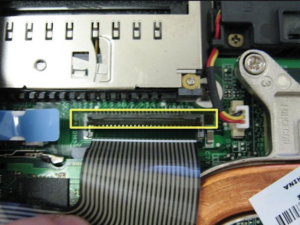
    • The middle part of my power connector had sheared away from its solder points on the motherboard.

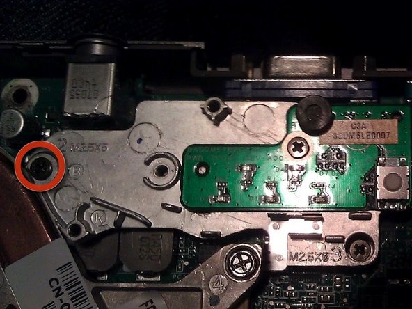
    • I had to use a bit of flux, but I managed to re-tin all three contact point on the motherboard, as well as the pins in the connector.

    • I re-soldered the whole thing and used my trusty hot glue gun to encase the whole connector to prevent it from happening again anytime soon.

ゴール

6 の人々がこのガイドを完成させました。

作成者

4人の作成者と共同で作成されました。

otrebla

メンバー登録日: 01/08/11

323 ポイント

1ガイドが承認済み

0 件のコメント

コメントを追加

統計データ:

過去 24時間: 0

過去 7 日: 10

過去 30 日: 25

今までの合計 9,696