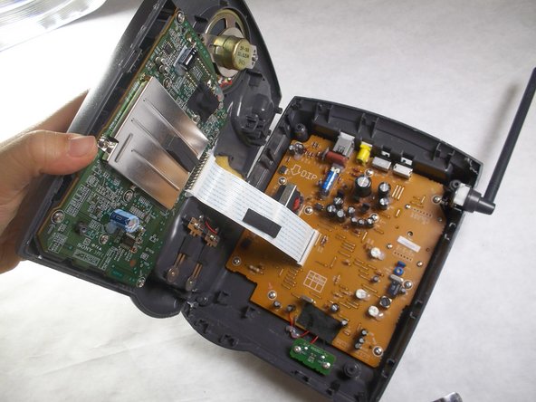
メインコンテンツにスキップ

Charging Component on the Base Replacement

必要な工具と部品

  1. Charging Component on the Base Replacement, Base: 手順 1、 1の画像 1
    • Turn the base over. You will see four 11mm Phillips #0 screws, one in each corner.

    • Use a screwdriver to remove all four 11mm Phillips #0 screws.

  2. Charging Component on the Base Replacement: 手順 2、 2の画像 1 Charging Component on the Base Replacement: 手順 2、 2の画像 2
    • Locate an easy seam for entry and insert the metal spudger to separate the plastic. Use the spudger in multiple places if necessary.

    • Opening the base may require exerting significant force as it is bound together tightly. This step can be dangerous.

    • The spudger is designed to make this step easier.

  3. Charging Component on the Base Replacement, Charging Component on the Base: 手順 3、 2の画像 1 Charging Component on the Base Replacement, Charging Component on the Base: 手順 3、 2の画像 2
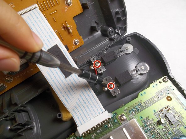
    • Locate the charging component towards the bottom of the grey, plastic, phone-shaped extrusion. It is composed of two metal pieces; each is fastened by a 5mm Phillips #0 screw.

    • Remove both 5mm Phillips #0 screws to release the metal pieces.

  4. Charging Component on the Base Replacement: 手順 4、 1の画像 1
    • Cut the black and red wires to finish removal, and then solder your new replacement component.

    • For more help on soldering, please refer to the iFixit Solder and Desolder Guide.

終わりに

To reassemble your device, follow these instructions in reverse order.

ある他の人がこのガイドを完成しました。

作成者

3人の作成者と共同で作成されました。

Han Shih

メンバー登録日: 09/29/16

361 ポイント

4のガイドは作成済み

チーム

IUPUI, Team 3-3, Harley Fall 2016 IUPUI, Team 3-3, Harley Fall 2016人のメンバー

IUPUI-HARLEY-F16S3G3

4 メンバー

17のガイドは作成済み

0 件のコメント

コメントを追加

統計データ:

過去 24時間: 0

過去 7 日: 0

過去 30 日: 0

今までの合計 299