メインコンテンツにスキップ

このバージョンは誤った内容を含んでいる可能性があります。最新の承認済みスナップショットに切り替えてください。

必要な工具と部品

  1. この手順は未翻訳です。 翻訳を手伝う。

    : 手順 1、 3の画像 1 : 手順 1、 3の画像 2 : 手順 1、 3の画像 3
    • Remove the strap from the camera by pulling the thin cord out, creating a small loop, then pushing the thicker cord back through this loop.

  2. この手順は未翻訳です。 翻訳を手伝う。

    : 手順 2、 3の画像 1 : 手順 2、 3の画像 2 : 手順 2、 3の画像 3
    • Remove the two Phillips screws (2.83 mm) from the left side panel of the camera casing.

    • The left panel can now be removed. However, one piece of tape attaches it to the camera, so a spudger may be required to ease the panels off.

    • Repeat for the right side panel of the camera.

    • Keep track of which screws go where. There are a couple sets of screws to take out and they are all small and look the same.

  3. この手順は未翻訳です。 翻訳を手伝う。

    : 手順 3、 3の画像 1 : 手順 3、 3の画像 2 : 手順 3、 3の画像 3
    • Remove the six Phillips screws (3.69 mm) from the bottom of the camera casing.

  4. この手順は未翻訳です。 翻訳を手伝う。

    : 手順 4、 3の画像 1 : 手順 4、 3の画像 2 : 手順 4、 3の画像 3
    • Remove the two Phillips screws (2.79 mm) on the left side of the camera where the metal panel used to be.

    • Repeat for the two Phillips screws (2.79 mm) right side of the camera.

  5. この手順は未翻訳です。 翻訳を手伝う。

    : 手順 5、 2の画像 1 : 手順 5、 2の画像 2
    • With the LCD screen facing up towards you, start at the bottom of the camera and gently pull off the back of the casing.

  6. この手順は未翻訳です。 翻訳を手伝う。

    : 手順 6、 3の画像 1 : 手順 6、 3の画像 2 : 手順 6、 3の画像 3
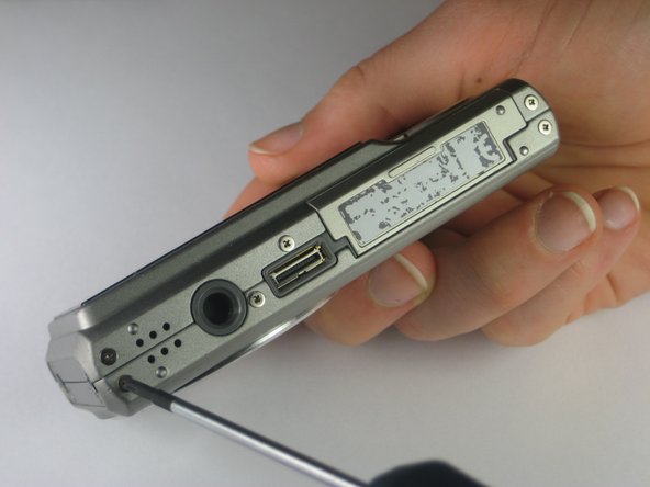
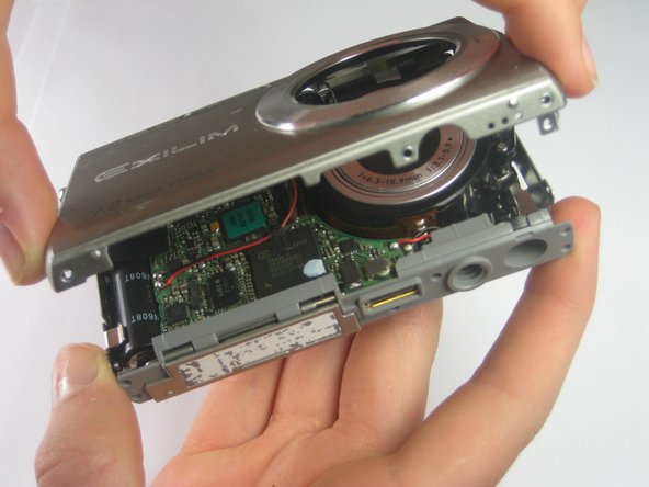
    • With the front side (with the lens) facing up towards you, start at the bottom of the camera and gently pull off the front of the casing.

    • The nob that previously held the camera strap will no longer be attached to the camera once you remove the camera casing. When putting the camera back together, remember to put the nob back into position before replacing the casing.

  7. この手順は未翻訳です。 翻訳を手伝う。

    : 手順 7、 2の画像 1 : 手順 7、 2の画像 2
    • Slide the labeled piece toward the LCD screen and release.

    • The tab will spring open.

  8. この手順は未翻訳です。 翻訳を手伝う。

    : 手順 8、 2の画像 1 : 手順 8、 2の画像 2
    • Look at the bottom of the camera. Take out the Phillips screw (1.77 mm) holding on the bottom plastic piece.

    • The bottom plastic piece is held on to the main frame of the camera only by two thin wires.

  9. この手順は未翻訳です。 翻訳を手伝う。

    : 手順 9、 2の画像 1 : 手順 9、 2の画像 2
    この手順で使用する道具:
    Tweezers
    $4.99
    購入する
    • Orient the camera with the lens facing up and the flash towards you for the clearest visibility.

    • Using a pair of tweezers, gently move the red and black wires away from the lens.

  10. この手順は未翻訳です。 翻訳を手伝う。

    : 手順 10、 3の画像 1 : 手順 10、 3の画像 2 : 手順 10、 3の画像 3
    • Using tweezers or your finger nails, pull up the brown flaps where the three orange film strips meet the circuit board.

    • Use the tweezers to pull all three orange film strips out of each port. The strips should come out easily.

  11. この手順は未翻訳です。 翻訳を手伝う。

    : 手順 11、 3の画像 1 : 手順 11、 3の画像 2 : 手順 11、 3の画像 3
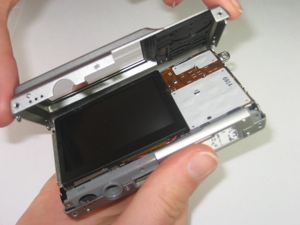
    • Flip the camera over to the side with the LCD screen.

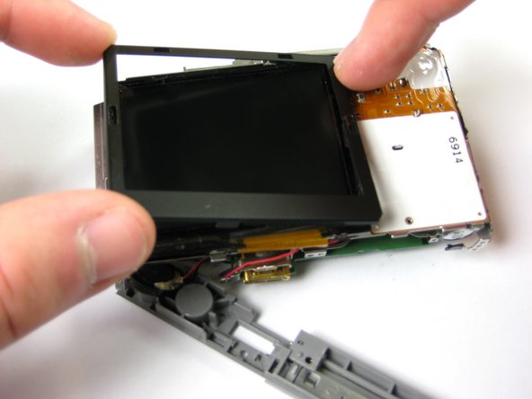
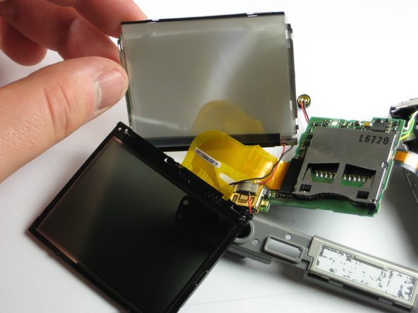
    • Gently remove the plastic cover that borders the LCD screen starting with the top left corner, then the bottom left corner, and finally the bottom and top right corners.

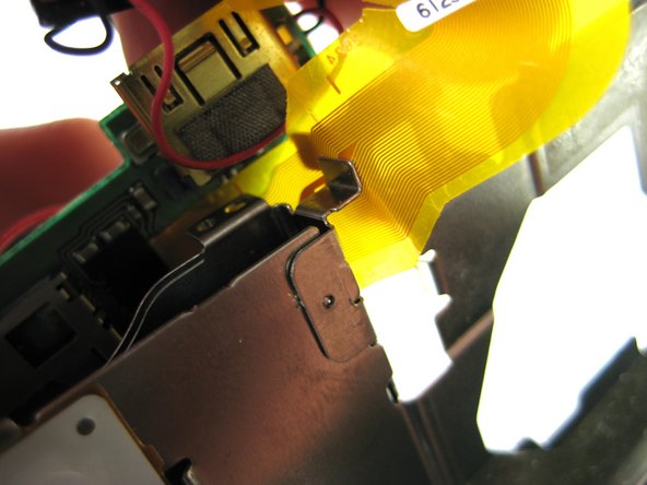
    • The LCD screen is now loose from the camera; it should only be connected by a gold strip that attaches to the circuit board.

  12. この手順は未翻訳です。 翻訳を手伝う。

    : 手順 12、 1の画像 1
    • Turn the camera back to the front side, with the lens facing up and the LCD facing down.

    • Remove the Phillips screw (3.30 mm) located below the flash on the circuit board.

  13. この手順は未翻訳です。 翻訳を手伝う。

    : 手順 13、 3の画像 1 : 手順 13、 3の画像 2 : 手順 13、 3の画像 3
    • At this point, the LCD screen and the circuit board are only attached to the camera by a thin gold strip on the far left of the circuit board.

    • Slide the gold strip that connects the LCD screen to the circuit board through the small gap at the bottom of the camera.

  14. この手順は未翻訳です。 翻訳を手伝う。

    : 手順 14、 2の画像 1 : 手順 14、 2の画像 2
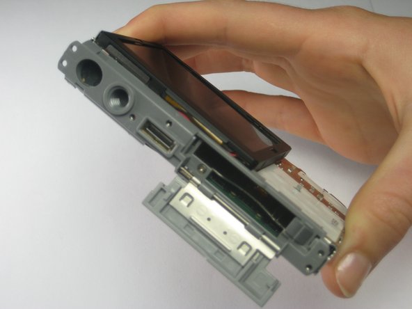
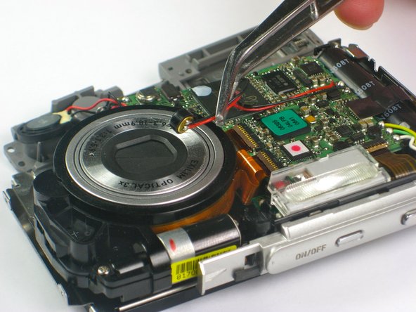
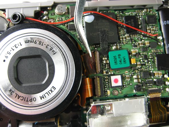
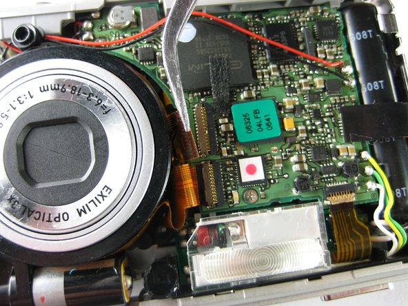
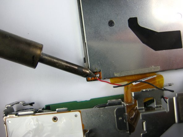
    • Using a soldering station and solder wick or other solder removing instrument, remove the solder holding the two wires of the LCD screen to the circuit board.

    • You have now completely removed your LCD screen. It can now be replaced or cleaned.

ゴール

ある他の人がこのガイドを完成しました。

作成者

6人の作成者と共同で作成されました。

Paul Fallon

メンバー登録日: 04/10/12

141 ポイント

6のガイドは作成済み

チーム

Cal Poly, Team 17-28, Amido Spring 2012 Cal Poly, Team 17-28, Amido Spring 2012人のメンバー

CPSU-AMIDO-S12S17G28

4 メンバー

14のガイドは作成済み

0 件のコメント

コメントを追加

統計データ:

過去 24時間: 2

過去 7 日: 4

過去 30 日: 33

今までの合計 1,951