このバージョンは誤った内容を含んでいる可能性があります。最新の承認済みスナップショットに切り替えてください。
必要な工具と部品
-
-
この手順は未翻訳です。 翻訳を手伝う。
-
Using the plastic opening tool, carefully pull up the rubber grip around the port side of the camera.
-
Remove the four different sized screws located beneath the rubber grip.
-
6 mm Phillips #PH00 screw.
-
3.4 mm Phillips #PH00 screw.
-
3.9 mm Phillips #PH00 screw.
-
2.2 mm Phillips #PH00 screw.
-
-
この手順は未翻訳です。 翻訳を手伝う。
-
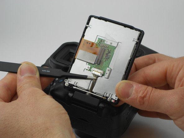
Next the wires are able to come off.
-
The RED arrows indicate a small hinge locking the wire in. To remove the wire, follow the same steps taken to remove the wire in the prior steps.
-
The ORANGE markers indicate that you need to lift the wire up and off of the motherboard. Using the opening tool, follow the same steps used to remove the swivel screen wire.
-
Next it is recommended that you use tweezers to carefully remove all hinged wires as demonstrated by the YELLOW arrow on the second image in this step.
-
-
この手順は未翻訳です。 翻訳を手伝う。
-
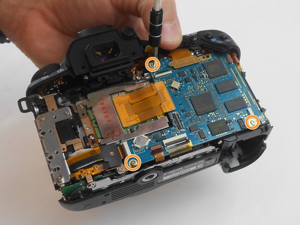
With the motherboard lifted, remove the indicated wire by using a plastic opening tool.
-
With the first bottom wire removed, the motherboard can be lifted higher, showing two more hidden wires.
-
Remove the wire indicated by the ORANGE arrow by undoing a hinge and sliding the wire out.
-
Remove the wire indicated by the YELLOW arrow by gently pulling it straight out of the socket it is seated in.
-


14 の人々がこのガイドを完成させました。
チーム

USF Tampa, Team 16-6, Wollert Fall 2015 USF Tampa, Team 16-6, Wollert Fall 2015人のメンバー
USFT-WOLLERT-F15S16G6
3 メンバー
14のガイドは作成済み
3 件のコメント
Dear Tyler, there is no need to remove the lcd, the camera can be easily repared by removing the back cover and than loosening the conectors and replacing the motherboard,there is no use in removing the lcd.