メインコンテンツにスキップ

Bose QuietComfort 25 Motherboard Replacement

必要な工具と部品

  1. Bose QuietComfort 25 Motherboard Replacement, Motherboard: 手順 1、 1の画像 1
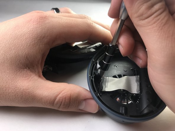
    • Begin repair by removing the ear cushion.

    • The cushion is held on by a few small plastic clips. Pry carefully with plastic opening tool or fingernails.

  2. Bose QuietComfort 25 Motherboard Replacement: 手順 2、 1の画像 1
    • Next, remove the soft lining behind the cushion. This is held on with adhesive and is easily removed by hand.

  3. Bose QuietComfort 25 Motherboard Replacement: 手順 3、 3の画像 1 Bose QuietComfort 25 Motherboard Replacement: 手順 3、 3の画像 2 Bose QuietComfort 25 Motherboard Replacement: 手順 3、 3の画像 3
    • Once the soft lining is removed from behind the ear cushion, two screws will be exposed.

    • Carefully remove the two 5 mm screws with a precision screwdriver (PH00) and put aside.

  4. Bose QuietComfort 25 Motherboard Replacement: 手順 4、 1の画像 1
    • Flip the earphones back over and carefully pry around the outside cover of the earpiece.

    • Try a plastic opening tool before moving on to harder metal tools.

    • This cover will come loose with moderate pressure.

  5. Bose QuietComfort 25 Motherboard Replacement: 手順 5、 3の画像 1 Bose QuietComfort 25 Motherboard Replacement: 手順 5、 3の画像 2 Bose QuietComfort 25 Motherboard Replacement: 手順 5、 3の画像 3
    • There are 3 screws holding the motherboard to the earpiece.

    • Remove these screws to make the next step easier.

  6. Bose QuietComfort 25 Motherboard Replacement: 手順 6、 1の画像 1
    • Once the motherboard is exposed, all of the soldered connection will need to be removed.

    • Be careful of this step and take note of the position of each wire.

    • This should only be attempted by someone with experience soldering small components, as irreparable damage may be result from improper methods. For help with this step see this guide on はんだ付けとはんだ除去の作業ガイド

  7. Bose QuietComfort 25 Motherboard Replacement: 手順 7、 1の画像 1
    • After removing all the soldered joints, the motherboard can be removed by hand.

    • The connections will all need to be re-soldered into their respective locations.

終わりに

To reassemble your device, follow these instructions in reverse order.

6 の人々がこのガイドを完成させました。

作成者

2人の作成者と共同で作成されました。

Samuel Coss

メンバー登録日: 03/26/18

339 ポイント

1ガイドが承認済み

チーム

IUPUI, Team S2-G3, Harley Spring 2018 IUPUI, Team S2-G3, Harley Spring 2018人のメンバー

IUPUI-HARLEY-S18S2G3

3 メンバー

6のガイドは作成済み

0 件のコメント

コメントを追加

統計データ:

過去 24時間: 0

過去 7 日: 24

過去 30 日: 123

今までの合計 11,067