メインコンテンツにスキップ

このバージョンは誤った内容を含んでいる可能性があります。最新の承認済みスナップショットに切り替えてください。

必要な工具と部品

  1. この手順は未翻訳です。 翻訳を手伝う。

    : 手順 1、 1の画像 1
    • Turn your Blackberry Storm 9500 onto its back side, and remove the battery door & battery.

  2. この手順は未翻訳です。 翻訳を手伝う。

    : 手順 2、 1の画像 1
    • Remove the 2 screws (T6) under the battery compartment they are located as shown in red.

  3. この手順は未翻訳です。 翻訳を手伝う。

    : 手順 3、 1の画像 1
    • Turn the Blackberry Storm 9500 around and pry off the microphone cover at the top using a safe pry tool.

  4. この手順は未翻訳です。 翻訳を手伝う。

    : 手順 4、 1の画像 1
    • Remove the two screws(T6) as shown.

  5. この手順は未翻訳です。 翻訳を手伝う。

    : 手順 5、 1の画像 1
    • Flip it back over to the back of the phone, and remove the plastic lens on top of the camera & flash. This is held in place by some adhesive, so use a safe pry tool to remove as shown.

  6. この手順は未翻訳です。 翻訳を手伝う。

    : 手順 6、 1の画像 1
    • Once the plastic piece is removed, unscrew the two torx screws underneath it.

  7. この手順は未翻訳です。 翻訳を手伝う。

    : 手順 7、 3の画像 1 : 手順 7、 3の画像 2 : 手順 7、 3の画像 3
    • Now use a safe pry tool, and go along the edges of the phone to release the clips to open the housing. There are a total of 6 clips, 3 on each side.

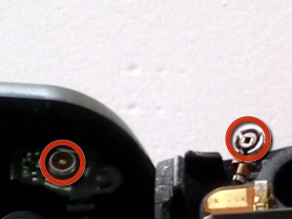
    • There is a small cap connection that connects the antenna to the logic board as pictured.

  8. この手順は未翻訳です。 翻訳を手伝う。

    : 手順 8、 1の画像 1
    • Once you have worked you way all the way around the device with the safe pry tool you can now separate the two pieces of the housing.

    • *Be sure to remove the antenna cable in the top portion of the housing. You will need to reattach this when you repair the phone*

  9. この手順は未翻訳です。 翻訳を手伝う。

    : 手順 9、 1の画像 1
    • Now remove the logic board & LCD assembly from the rear housing. Be gentle, and do not use excessive force.

  10. この手順は未翻訳です。 翻訳を手伝う。

    : 手順 10、 2の画像 1 : 手順 10、 2の画像 2
    • Flip the logicboard around so that it is sitting on top of the screen, now remove the two ribbon cables for the LCD & Digitizer.

  11. この手順は未翻訳です。 翻訳を手伝う。

    : 手順 11、 1の画像 1
    • Put your broken assembly to the side, and now install your new one following the past steps in reverse.

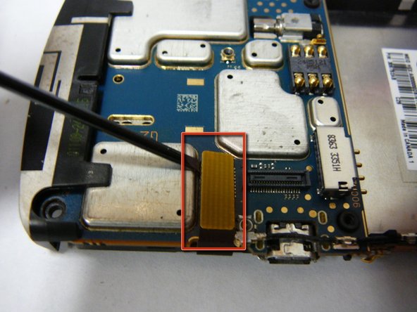
    • Before ordering your new part, check the number on your existing LCD, it will either be V.014 or V.024. (Shown in blue)

ゴール

13 の人々がこのガイドを完成させました。

作成者

2人の作成者と共同で作成されました。

Josh Forester

メンバー登録日: 11/28/10

2,497 ポイント

10のガイドは作成済み

0 件のコメント

コメントを追加

統計データ:

過去 24時間: 2

過去 7 日: 12

過去 30 日: 17

今までの合計 21,109