はじめに
You will be able to break the tablet down to the circuit board and disconnect the components connected to the circuit board.
必要な工具と部品
-
-
-
Start by bending the tablet back at the top white-colored portion to expose an opening between the back cover and the tablet body.
-
Wedge a plastic opening tool into the opening and push it down to force the back cover off.
-
Move along the top edge of the tablet and repeat the step above.
-
Pull the back cover away from the tablet body to completely remove it.
 FixBotに聞いてみる
-
-
-
-
-
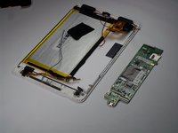
With the back cover removed, you can now see the battery.
-
You will need a soldering/desoldering kit to desolder the 3 battery leads to the circuit board.
-
-
-
-
-
The microphone is located in the bottom center of the tablet.
-
Remove the black tape holding the wires down.
-
Remove the black tape holding the microphone in place.
-
The microphone is now exposed and can be gently pulled out of the socket.
-
-
-
You will need a soldering/desoldering kit to desolder the 2 leads where the microphone connects to the circuit board.
-
-
-
-
-
-
The speakers are located towards the bottom left and bottom right corners of the tablet.
-
If not already done, remove the black tape holding the wires down.
-
Wedge a spudger underneath the speaker in its socket, near where the wires are connected. You can then pry out the speakers.
-
-
-
You will need a soldering/desoldering kit to desolder the 4 leads where the speakers connect to the circuit board.
-
-
-
-
-
To get to the front camera, you will first need to remove the top panel.
-
Unscrew two 2.25 mm Phillips screws with a #00 screwdriver from the top plastic panel to remove it.
-
-
-
Once unscrewed, use a spudger to pop the panel off by wedging it underneath the panel.
-
-
この手順で使用する道具:Tweezers$4.99
-
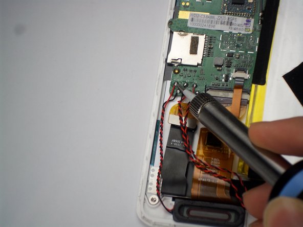
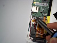
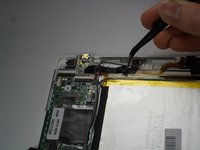
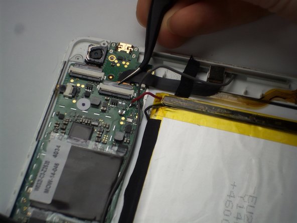
First, use plastic coated tweezers to pull up the black release tab.
-
Pull on the black connector with tweezers as close as possible to the white connector base, making sure not to pull on the connector base.
-
Next, use the tweezers to peel off the tape holding down the connector to the front camera.
-
The front camera can now be removed from its socket.
-
-
-
-
この手順で使用する道具:Tweezers$4.99
-
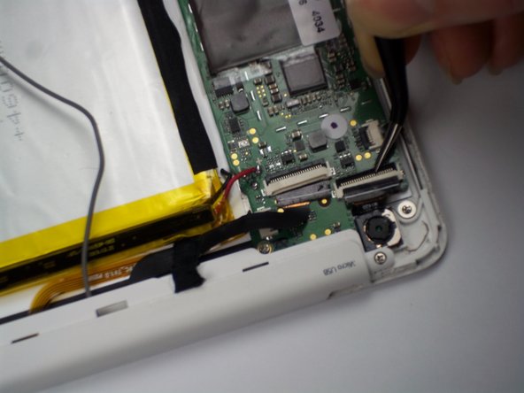
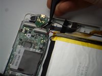
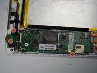
After removing the top panel, battery, speakers, microphone, and front camera from the tablet, you will also need to use the tweezers to remove the connectors indicated in the same method as the previous step.
-
-
-
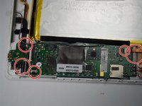
Using a Phillips screwdriver, remove three 2.25 mm screws from the circuit board.
-
The circuit board can now be removed from the tablet.
-
-


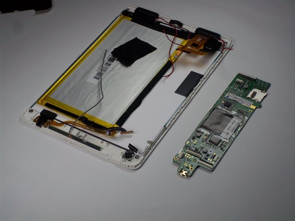
To reassemble your device, follow these instructions in reverse order.
ある他の人がこのガイドを完成しました。
チーム

Baylor, Team 4-1, Williams Spring 2015 Baylor, Team 4-1, Williams Spring 2015人のメンバー
BU-WILLIAMS-S15S4G1
3 メンバー
12のガイドは作成済み