はじめに
こんにちは!
このガイドでは、IPSスクリーンとアダプターをゲームボーイアドバンスに取り付ける方法を説明します。
必要な工具と部品
-
-
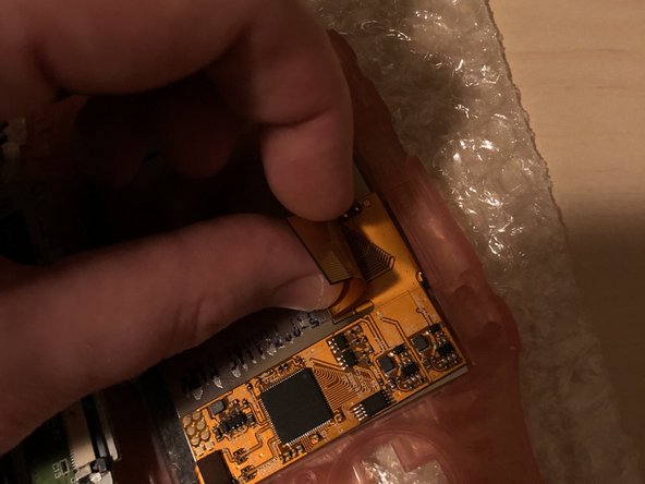
スパッジャー、ピンセットもしくは爪先で、側面のグレーのタブを上方に(PCBの上端に向かって)引いて、LCDリボンポートのラッチを外します。
-
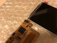
LCDリボンポートが外れたら、LCDリボンは簡単に側面から取り出せます。
Guide does not indicate that the ribbon cable port should be UNLATCHED before attempting to remove the ribbon cable, I strongly suggest revising this as someone unfamiliar with these style of ports may assume that the ribbon cable is a compression fit and just needs to be "pulled" free of the port.
This is a terrible idea that will potentially result in tearing the ribbon! Please consider revising guide to add a step to indicate the proper method/detail for unlatching the LCD ribbon port! Thanks :)
-
-
-
-
スパッジャーを使ってフロントパネルからスクリーンを持ち上げます。スパッジャーをDパッド左側の隙間に差し込みます。
This is a BAD place to pry on a functioning LCD. I used this exact method, slowly and carefully, and my LCD shattered.
Instead, remove the lens (it’s worth it to sacrifice the lens adhesive to save your LCD), and gently and slowly press with a gloved thumb on a corner to push it through from the front of the Game Boy. Let the adhesive release itself, don’t force it. If the room is super quiet, you should be able to hear a faint peeling sound, even if you can’t see anything moving. That means you’re doing it right; just wait and it will release.
Actually you can just pry under the ribbon cable. The LCD has a metal frame there that allowed me to slowly and carefully pry from that point without (re)breaking my LCD.
Yep. Same thing just happened to me :(
-
-
-
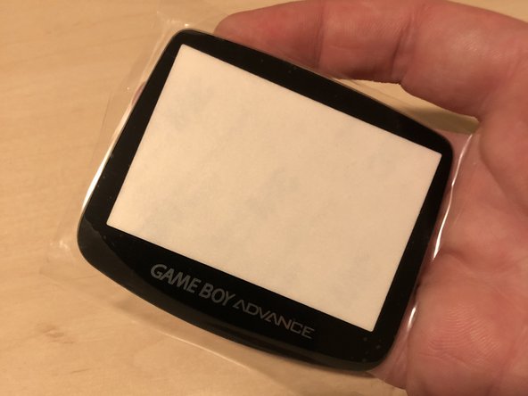
まず、すべて開梱し、パーツが揃っているかどうかを確認します。
-
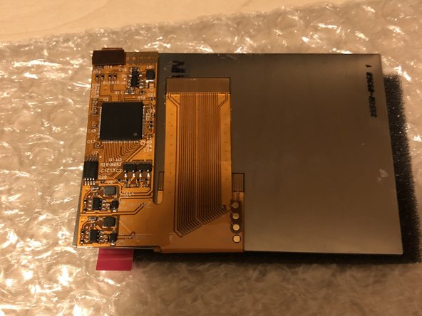
スクリーンを接続する必要があるコネクタは赤丸で囲まれています。 これはアダプター上の唯一のコネクタです。
-
LCD ケーブルをコネクタにまっすぐ押し込みます (正しく位置合わせされていることを確認してください。そうしないと、コネクタが損傷する可能性があります)。
-
-
-
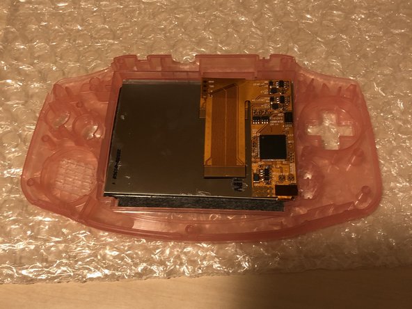
アダプターを画面の裏側に折り、すべてが正しく所定の位置に収まっているかどうかを確認します。 1枚目の画像のようになればOKです。
-
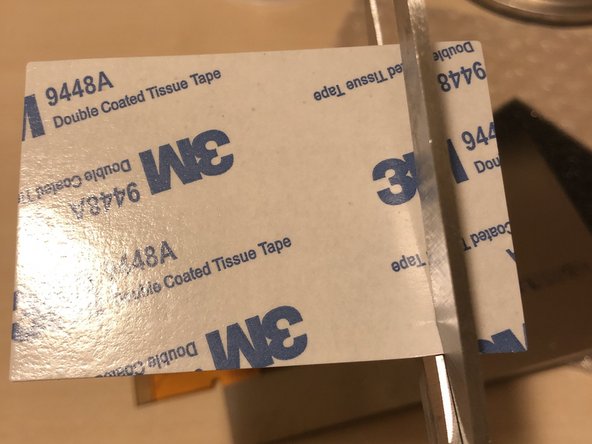
次の作業のために両面テープを切って準備します。
“A layer of insulating plastic film on the back of the screen Don't tear it off.”
This is a warning from the Funny Playing installation guide.
The kit shown in this guide appears to use a different ribbon/interface from than the one sold by FP. But the LCD looks exactly the same. If you havn’t experienced negative side effects from doing this, I would consider the double sided tape step you mention below a mitigating factor.
Hi Jon!
Thanks for your comment!
At this moment it still works fine for all the GBA’s I modded.
As it won’t have any affect if you leave the plastic foil be at the backside, I’ll remove the step from the guide to prevent any damage which can be done if you remove it.
Thanks again for thinking with me!
-
-
-
両面テープの片面をIPSスクリーンの裏側に貼り付けます(アダプターに合わせてください)。
-
両面テープから紙を剥がします
-
そしてアダプターを画面の裏側に貼り付けて下さい。3枚目の画像のようになればOKです。
-
-
-
画像に示すように、40ピンケーブルをアダプターの下に折ります。(32ピンのマザーボードがある場合にのみ適しています!!)。
-
40ピンのマザーボードの場合は、ケーブルをそのままにしておくだけで、追加の調整は必要ありません
-
-
-
選択肢は2つあります。オプション1:あらかじめトリミングされた外装を購入します。オプション2:外装を自分でトリミングします。非常に重要なステップなので、事前にトリミングされた外装を用意しています。 このガイドは、事前にトリミングされた外装のみを対象としています。 独自の外装をトリミングする必要がある場合は、Googleで何をトリミングする必要があるかを確認し、完全にトリミングされていることを確認してください。
-
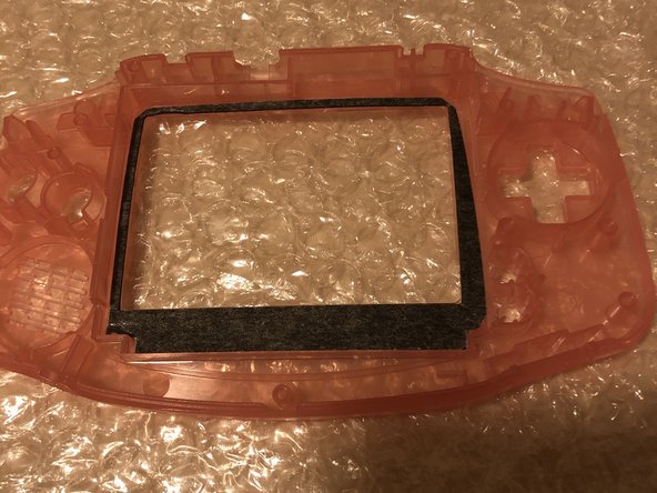
画像2に示すように、外装に両面テープを貼り付けます。適切な位置にあることを確認してください。
-
-
-
IPS スクリーンの前面からホイルを取り外します。
-
続行する前に、全てのパーツにゴミが完全に付着していないことを確認してください。
-
IPS スクリーンを外装内に配置します。 画像2に示すように正確に配置してください。
-
-
-
プラスチックの透明バーを2本取ります。細いバーとやや太いバーがあります。
-
薄いプラスチックのバーを外装の左側に置きます。完全に収まらない場合は、そのままにしておきます。そして、太いバーは外装の下側に配置する必要があります。
-
-
-
外装を裏返して、IPS スクリーンが適切に設置されているかどうかを確認します。 これは、画面にゴミが付着していないことを確認するための最後の機会です。
-
新しいレンズを取り出して挿入し、取り付ける前に全てのパーツに埃がないことを確認してください。
-
-
-
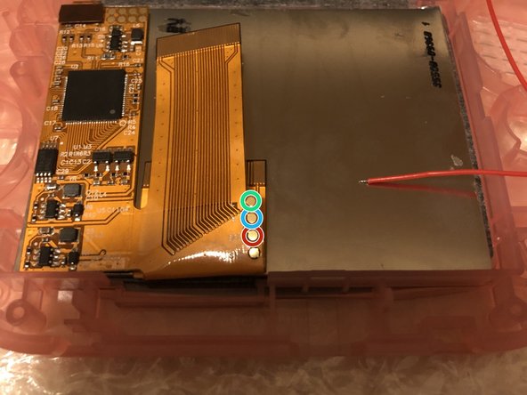
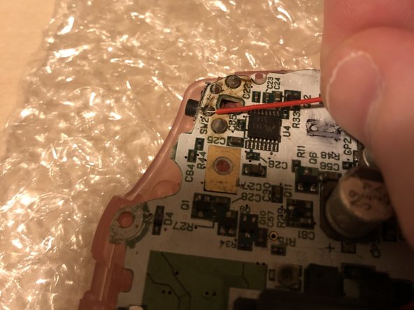
リボンケーブルを確認してください。 3つの金色の丸いパッドが見つかり、その横に次の文字が書いてあるはずです。 L、R、SEL。
-
赤丸=SEL(セレクト)
-
青丸 = R
-
緑の丸 = L
-
-
-
2枚目の画像に示すように、パッドにはんだを付けます。
-
3本のケーブルをパッドにはんだ付けします。3つの異なるケーブルの色を使用することをお勧めしますが、キットに赤いケーブルしかない場合は、それを使用してください。
-
-
-
マザーボード上のTP2パッドを見つけます。パッドにはんだを付けます。
-
SELケーブルをマザーボードのTP2パッドにはんだ付けします。
-
仕上げにテープを貼ってもいいでしょう。
-
-
-
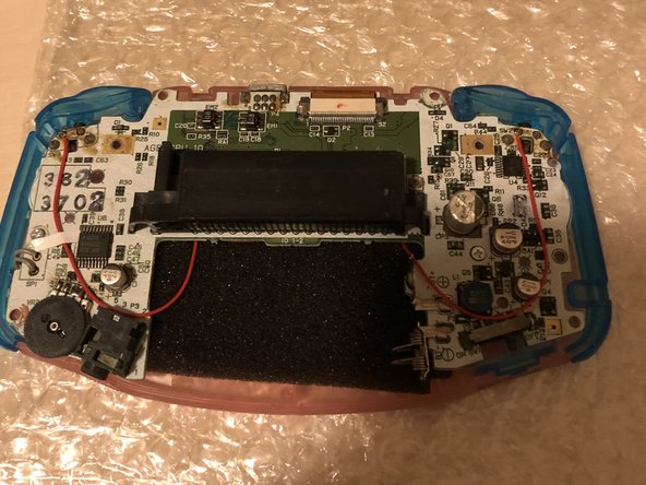
キットに黒いスポンジが入っている場合は、マザーボードを取り付ける前のこの時点でマザーボードを取り付けてください。 これは必須ではありませんが、マザーボードとアダプターにはんだ付けされたケーブルを保護します。
-
赤丸のネジ2本を取り付けます。 注意してください。
-
2つの緑色の矢印は、LとRのケーブルの配線方法を示しています。Lケーブルは右側に、Rケーブルは左側に接続する必要があります。 (これは、画像のようにゲームボーイを裏返して作業しているため、左右が逆になっているからです)!
-
最後の画像は、すべてがうまくいっていて、次の作業に進む準備ができている時を示しています。
-
一部のモデルには、青い丸で囲まれた3番目のネジがあります。
-
-
-
Rケーブルを左側にハンダ付けします。 最初の画像を確認して、どのはんだパッドにはんだ付けする必要があるかを確認してください。
-
Lケーブルを右側にはんだ付けします。 2番目の画像を確認して、どのはんだパッドにはんだ付けする必要があるかを確認してください。
-
赤い矢印で問題がないか確認してください。 最後の写真のようであれば、準備完了です。
-
-
-
ケーブルが希望の位置に収まらない場合は、再度テープを使用してください。
-
他のボタンも付けてみましょう!
-
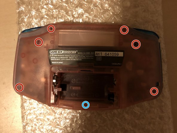
赤丸部分のネジを元に戻します。 青い丸で囲まれたネジは他のネジよりも小さいことに注意してください。
-
-
-
電池を入れてゲームボーイをテストします。1枚目の画像のようになれば成功です!
-
SELECTボタンを押しながらLボタンを押すと明るさが下がります。 SELECTボタンを押しながらRボタンを押すと明るくなります。
-
ゲームを入れて動作するかテストします。 ゲームが正常に動作している事は、IPS スクリーンも正常に動作していることを意味します!
-


以上です! すべてがうまくいけば、GBAにバックライト付きスクリーンが搭載されているはずです。
以上です! すべてがうまくいけば、GBAにバックライト付きスクリーンが搭載されているはずです。
7 の人々がこのガイドを完成させました。

チーム

7 件のコメント
Hi I already have a gba with the ips backlight installed already and I'm looking to replace the buttons, shell, and, screen lens. Will I need to solder anything or do I just replace it?
Hi! No, you can take out the motherboard with the adapter, BUT be sure you unplug the screen from the adapter first. When you did this, transfer the screen first. When the screen sits flush, connect it to the adapter and build it back in :). Good luck!
did every step but when i turn on my gameboy i get a blackscreen with backlight but no video. i think my ips display is broken.
Hi!
I regonize this issue as this did happened to me too (doing a lot of IPS Mods and had this issue 2 times of all the GBA’s I modded). It’s not the IPS screen, it’s the adapter which is broken. When you replace the adapter for a new one, it will work with your installed IPS screen.
Hi - I have this Mod ALMOST working. My problem: when I hit "Select" it acts as though I'm holding "Select + L Shoulder" (it dims) and the L Shoulder button itself doesn't seem to work at all. Any tips on what I did wrong? The R Shoulder works and select + R brightens as it should.