
Do have the Alcatel 5002f electrical diagrams?
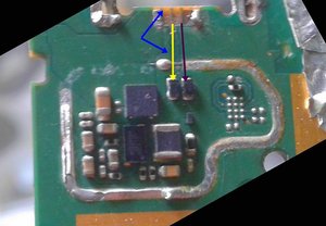
This the charge sector and the micro usb port it's missed 3 pins, in the middle I need know where the circuit of any pin is connected in the board?

この質問は役に立ちましたか?
スコア
1

評価: 13
![]() 4
4
This the charge sector and the micro usb port it's missed 3 pins, in the middle I need know where the circuit of any pin is connected in the board?
この質問は役に立ちましたか?
評価: 13
![]() 4
4
I already remove the usb conector, but it's still not working
このアンサーは役に立ちましたか?
@defenessetdkhda I am not understanding what you are trying to say. You will need your USB connector on the circuit board........
Oldturkey03, I'm sorry I don't speak English very well. But I will be annoying again. I have few questions.
I would like to know if which of the components, if damaged, could cause the phone to not turn on after a repair?
I know that the usb connector pins give rise to 5 different circuits (GND, Vbus, D+, D-, Vbat) in this case I would like to know which components are in each circuit and if I hear a failure in one of these circuits, what damage will it do in the motherboard ?
I also know that smartphones have 4 sectors (load sector, network sector, memory and processing sector) what are the consequences of the malfunction of each sector on the board? and finally, what are the reasons why a smartphone board doesn't turn on?
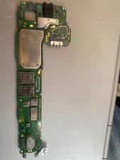
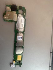
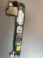
If you scroll down a little you will see the photo of the smartphone card that is causing me headaches.
@defenessetdkhda Got it. So it's more than just the USB connector. That is a lot tougher since that would really require the schematics and a component layout. We'll just have to continue to search for it and hopefully we'll find something about this.
Thanks for your attention and support, I sent a message to the Alcatel industry asking for the Alcatel 5002f layout. I hope they answer me, when I receive the file I will sent to you.

評価: 791.3千
![]() 1.1千
1.1千
![]() 899
899
![]() 2.4千
2.4千
@defenessetdkhda any chance you can do another picture and just keep it focused. Looks like we can trace the connector with a slightly better picture. You would just have to solder some jumper wires. Right now it looks like this based on your image and teh traces. I would consider instead of trying to fix a new port on that to use a "rattail" cable and solder it to the places.
このアンサーは役に立ちましたか?
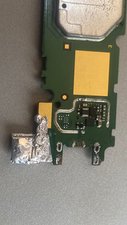
Thanks mas but it's really hard to. I'm trying to do it. I will sand and pictures of my work. You know whats is theses components?
@defenessetdkhda not without seeing it ibn close up. You may find it on other boards for Alcatel but since schematics are difficult to find for this model, it will be a challenge. The best thing to do in case like this is to find an exact motherboard for this phone and use that as a donor board for parts.
Thanks man, I'm sorry but sometimes my curiosity makes me very annoying, you could be my go-to in the electronics field, to be honest I'm a beginner and bewildered.
@defenessetdkhda no worries about being annoying, you are not. It's all good.
How you doing oldturkey03, I already had done the jump but the cellphone don't want power on. Now I don't know what I can do for solve this problem.
過去 24時間: 0
過去 7 日: 2
過去 30 日: 10
今までの合計 132
2 件のコメント
[image|3203375][image|3203376][image|3203374][image|3203377]
I already removed the charge conector, but it's still not working.
Defenesse Tdkhda さんによる
[image|3203375][image|3203376][image|3203374][image|3203377]
I already removed the charge conector, but it's still not working.
Defenesse Tdkhda さんによる