メインコンテンツにスキップ

Repair and disassembly information for amplifiers in home audio systems.

117回答 すべてを表示

Yamaha R-N803 has no power

I went to turn on my Yamaha R-N803 amplifier after moving it to a new location. When I pressed the power button, there was a pop/bang sound and a flash inside the unit. The standby power light turned was on for a few seconds and then turned off. Now, there’s no response from the unit at all. When I turn it on, absolutely nothing happens. No sound of relays, nothing on the display, etc. Completely dead.

Maybe I blew a fuse? Where should I begin looking for problems? A quick look inside the unit doesn’t show anything obviously wrong, but I’m also not sure exactly what to look for.

EDIT: A bunch of photos of the insides. I also tried replacing the fuse on the power delivery board, no dice there. The original fuse is just fine as well.

The whole thing:

Block Image

Power Delivery Board:
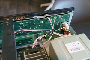
Block Image

Everything else:

Block Image

Block Image

Block Image

Block Image

Block Image

この質問に回答する 同じ問題があります

この質問は役に立ちましたか?

スコア 0
2 件のコメント

Joseph GReve "there was a pop/bang sound and a flash inside the unit. " never a good thing. Post some GOOD pictures of your boards etc. with your QUESTION. Let's see if we can assist you in finding out what happened. iFixitでの質問に画像を追加する方法

Make sure you'll have access to a multimeter (yes, inexpensive department store meter will work ;)

さんによる

@oldturkey03 - thank you so much for responding to my post. I realize it's been a few months since I originally posted it (life got in the way and I completely forgot about this), but I've added a bunch of hi-res photos and a few other details.

さんによる

コメントを追加

1 件の回答

最も参考になった回答

Hi @Joseph Greve

With the power connected to the receiver, in the power delivery board, check if there is +3.3VDC and/or +5.5VDC being supplied by the board with the fuse on it.

Here's a zoomed in image taken from the image you posted to show where I mean.

In other Yamaha receivers, the +3.3V and the +5.5V DC are usually used to supply the board which has the CPU on it which controls the receiver.

I can't find a service manual or a schematic for your model, so hopefully yours will be similar.

Block Image

(click on image to enlarge)

Be safety aware when testing as there is lethal AC power on the board with the fuse on it.

このアンサーは役に立ちましたか?

スコア 1

3 件のコメント:

@jayeff - I'll test it later today! I have a multimeter that I've used for simple things before, but what's the best way to check for the +3.3V and +5.5V? Obviously one multimeter lead will go on one of the wires highlighted, where would the other multimeter lead go?

さんによる

@jayeff - update! There does not appear to be 3.3V or 5.5V getting delivered from that power delivery board. What would the next steps be? Remove the power delivery board and inspect it visually?

さんによる

@Joseph Greve

Just curious if the "new location" that you moved to, uses the same mains voltage as your old location e.g. 120V AC or 240V AC etc as pressing the power button on a device with the wrong voltage attached e.g. 240V connected to a 120V device will cause a "bang" to occur?

You should be able to measure voltage between an earth point in the receiver (chassis or screw head) and the required test point.

You said that the fuse is OK but maybe you should verify that there is voltage on the output of the fuse.

This is where it is dangerous because it is mains supply AC voltage.

If there is (or even not) then you would have to remove that board and first visually inspect it and then start doing point to point testing with an Ohmmeter to find out how far the supply voltage path is getting into the board from the cord input pins.

さんによる

コメントを追加

回答を追加する

Joseph Greve さん、ありがとうございました!
統計データ:

過去 24時間: 3

過去 7 日: 16

過去 30 日: 28

今までの合計 237