メインコンテンツにスキップ

Model A1200 with 2.16 or 2.33 GHz Core 2 Duo processor

113回答 すべてを表示

iMac 24" A1200 power supply pinout?

Hi all!

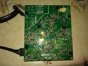
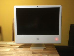
A friend of mine gave me a broken imac 24". I would like to recycle the power supply for another project, however i don't know the pinout, well i could easily find the Vcc with voltmeter. I just need to know which pin will switch on the unit, and if it's a "connect to Vcc" or "connect to ground" system.

Here some more

ref. SADP-220AF (A1200)

24v@4A and 12V@10,3A

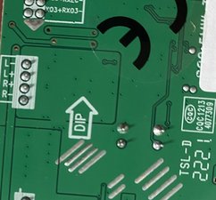
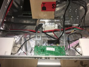
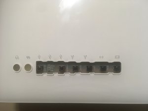
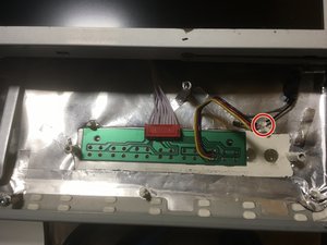
A few pics

Block Image

Block Image

Block Image

Block Image

Cheers!

回答がありました! 回答を表示 同じ問題があります

この質問は役に立ちましたか?

スコア 0
コメントを追加

7件の回答

ベストアンサー

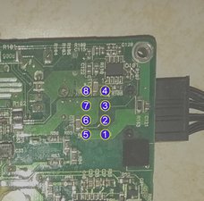
Quick feedback on my tests during the last couple of days

Block Image

iMac OFF

  1. 0v
  2. 3,3v
  3. 0v
  4. 0v
  5. 0v
  6. 12,1
  7. 12,1
  8. 25,3

iMac ON

  1. 0v
  2. 3,3v
  3. 2,3v
  4. 0v
  5. 0v
  6. 12,1
  7. 12,1
  8. 25,3

PIN-1 & 5 => O volt

PIN-2 => 3,3 volts

PIN-4 => unknown

PIN-6 & 7 => 12 volts

PIN-8 => 24 volts

  • PIN-3 is connected to what seems to be a temperature probe
  • My conclusion is this PSU has no switch ON/OFF,
  • It’s always powered up
  • It's been a few days now i'm using it on both 12/24v, and nothing to report

このアンサーは役に立ちましたか?

スコア 3
コメントを追加

Hi, can I use this PSU with M.NT68676.2 and LM240WU2-SLA1 to make external monitor? if yes then how?

--

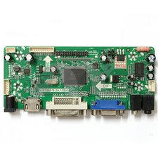
This image is of M.NT68676.2A and I have M.NT68676.2, but both looks same.

Block Image

--

M.NT68676.2 Inverter Connection Pins

Block Image

--

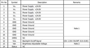
My screen LM240WU2-SLA1's Connection Pins

Block Image

--

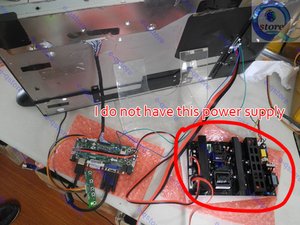
I want to use Mac's power supply instead of shown in below image:

Block Image

Can I use it?

このアンサーは役に立ちましたか?

スコア 0

4 件のコメント:

as long as you power the LCD controller with the right voltage/amperage, you can use any PSU you like,

i personaly use the same setup and it works well :)

さんによる

I am trying to do the same thing.

I connected my existing power supply, but cannot seem to get the display to function.

There is an output voltage jumper on the LCD control board. Do you leave it at 3.3V, or set it to 5V or 12V?

thanks.

さんによる

Yes, you can use the original iMac power supply. I have done this. But with some hassles. You really have a new question here, but the longer answer is to order the board with the correct firmware and cable set for your panel. Then connect the cables as follows: iMac pin 4 to four black wires going to inverter. iMac pin 8 to four red wires going to inverter. iMac pins 1 and 5 soldered to the two black wires going to the controller, and iMac pins 6 and 7 soldered to the red wires going to the controller.

さんによる

The hassle was that I never got the LM240WU2(SL)(A1) panel to work properly. It worked for 1 second, and then washed out into a barely visible white picture. I also have a iMac A1225 with the LM240WU2(SL)(B4) panel, and in desperation I tried that panel. It worked just fine, and the original (SL)(A1) worked just fine in the A1225, so I swapped them. The newer panel looks better anyway.

さんによる

コメントを追加

Answer 1:

You need just one +12V pin and one 0V or Ground pin that’s it.

Answer 2:

I think you need to use the power supply of the Mac to hook up the inverter.

Answer 3:

As long as the voltages match up and the amperage is equal or greater you are good to go. For example, if you need 12V 2A then you need to supply 12V and at least 2A, you could use 12V 4A if you wanted and it will still work.

このアンサーは役に立ちましたか?

スコア 0
コメントを追加
I managed to get it working on the first try with a late 2006 24-inch imac and a newer controller board that supports display port. Thanks to those who paved the way, using the original power supply.

このアンサーは役に立ちましたか?

スコア 0

1件のコメント:

Good night! Do you remember if you did "iMac pin 4 to four black wires going to inverter. iMac pin 8 to four red wires going to inverter. iMac pins 1 and 5 soldered to the two black wires going to the controller, and iMac pins 6 and 7 soldered to the red wires going to the controller" or can someone confirm that this is correct? Thanks 🙏🏼

さんによる

コメントを追加

Hello!

Can anyone confirm if this is correct? "iMac pin 4 to four black wires going to inverter. iMac pin 8 to four red wires going to inverter. iMac pins 1 and 5 soldered to the two black wires going to the controller, and iMac pins 6 and 7 soldered to the red wires going to the controller"

Thanks 🙏🏼

このアンサーは役に立ちましたか?

スコア 0

4 件のコメント:

Noooooooo.

Imac 1 and 5 (they are the same) one to two black wires to the controller, and other to four black wires going to inverter.(Negative)

iMac pin 8 to four red wires going to inverter OK. (+24v.)

iMac pins 6 and 7 to the red wires going to the controller OK. (+12v.)

Forget all other pins.

Ive just do it, and works well. The wires that came to me are very thin, you are doing well using all red and black wires.( Please dont use only one.)

I plan to put the card (video conectors) coming out from the ram slot.

And the buttons to the rear side, cutting "in line" all the imac´s outs.

There are colored caps to enlarge the buttons.

Thanks to all for the info.

Have a nice day.

さんによる

Thank you very much for the reply. I will do it the way you tell me, but in reality, pin 4, being 0V like pins 1 and 5, should also work in the other way that I said above, right?

Good idea how to place it.

Best regards

さんによる

Hi, ihadadream put: PIN-4 => unknown. ( It was a volt test measure)

Many parts of a circuit can be 0v sometimes but that dont mean they are connected to GND(-negative).

You can see clear in the photo that pins 1 and 5 are connected together with a big track. I cant test now pin4. Dont use it.

さんによる

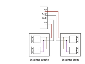
Thanks for the clarification! Another question, do you know the pinout of the speakers? I have seen that each of the speakers has 4 cables. I found this video (https://www.youtube.com/watch?v=0pkJvtRM...) where they connect them to the LCD control board so that they work through HDMI but the colors on the 2006 model are different. If you can tell me I would appreciate it, best regards!

さんによる

コメントを追加

I added the image here, it doesn't leave me in the reply to the comment

Block Image

Update (02/19/24)

*This is the connector, so it forces me to connect it -++- right?

Block Image

Update (02/21/24)

On an IFIXIT page for the imac 2008 they put this color scheme for the speakers, putting black as positive and it is just the same connector as well. Would it be incorrect?

Block Image

このアンサーは役に立ちましたか?

スコア 0

7 件のコメント:

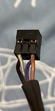
There are 2 speakers:

Black(-) and Grey(+) 8Ω

Pink(-) and Brown(+) 8Ω

I had "imagine" this "polarity" as Black is "always" negative.

I put them in pararell (++/-- 4 Ω).The ampli of the card is for 8Ω. Maybe better to connect them in serial(-+-+) doing 16Ω, (less power but more securety if you plan to use them at hight vol).

AAaaa I had use the original power button enlarging the cables and soldering to the button of the card.

And glued the led in the spaeker hole ( with cables).

Soon ill upload photos.

さんによる

Thanks for the reply. My board says "It's a 4Pin speaker connector, which you can connect to a pair of 4-ohm 3W or 5W LCD universal speakers" so I don't know if it will be enough or I will need a separate amplifier. I'll try it and post the result. Brilliant! I would like to see that too haha

さんによる

No. For example: left Channel:

L-(connector) to Black(-).

Gray(+) and Violet(-) together( to "nothing"),

and Brown(+) to L+ (connector).

さんによる

Or you can connect only 1 speaker for each channel. Choose the same colors, Black(-) and Grey(+), for example.

さんによる

Could be correct, and sure will work. I think the polarity is not critical in this case of low power. This is the parallel way.

Mine is working too.

さんによる

2件以上のコメントを表示

コメントを追加

画像の内容を見る:

Block Image

Block Image

Block Image

Block Image

このアンサーは役に立ちましたか?

スコア 0

4 件のコメント:

If you put the connector of the buttons in this way, you must invert the cables position.

さんによる

Nice job 👏🏻👏🏻 I have a question regarding the speakers, do you know what color combination the bass and tweeter are? I'm going to try using a crossover to improve the sound

さんによる

I dont find info about 2 way speakers. Are you sure? They seems to me equals.

さんによる

I made all the connections today and it worked. Thanks for the help and for answering all the questions. The only thing is that made a loud hum when the screen was on (showing image). Is that normal? (In the end I didn't connect the speakers because I realized one was broken). It's something a little scary. Before disassembling the imac, when I was using mac os x lion, the screen didn't make any noise.

さんによる

コメントを追加

回答を追加する

ihadadream さん、ありがとうございました!
統計データ:

過去 24時間: 2

過去 7 日: 11

過去 30 日: 108

今までの合計 4,784